German Auto Solutions has extensive experience in high performance engine building, engine machining and dyno tuning. Our specialty is in cylinder head flow development for four valve overhead cam engines.
Due to our efforts to concentrate on new product development, we are not currently taking in customer engine building, cylinder head or machining work. Even though we are not currently accepting outside engine work, our extensive knowledge and experience in that area always helps us in our design and engineering of new products.Below are some pictures of our engine machining equipment and development work.
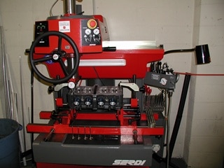
Serdi Valve Seat & Guide Machine, the industry standard for cutting high performance valve seats. This machine uses solid carbide pilots & 3 axis air floatation to perfectly center the valve seat cut to the valve guide. Three, four, five angle, or radiused seat cuts are made in a single operation using a custom ground carbide insert. Every seat will receive the exact same seat profile cut to the exact same depth. Experience on the flow bench allows us to know which type of seat works best in which application.
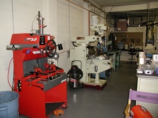
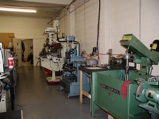
A couple of shots of our boring, honing, valve seat cutting and manual machining equipment. Some of our larger boring operations are performed in one of our CNC machining centers.
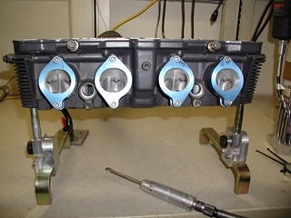
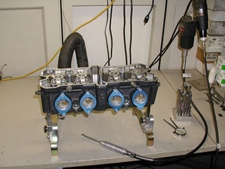
Some pictures of a cylinder head on the porting bench. We have a lot of experience with four valve over head cam heads. We use foot pedal controlled electric grinders rather than air grinders. Electric grinders have much more torque at low rpms and are much more controllable when doing detailed work on aluminum heads.
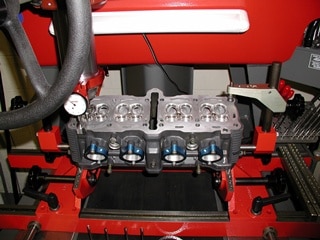
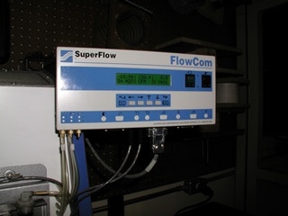
A BMW M54 head on our SuperFlow flow bench. Custom bore adaptors and radiused port adaptors are made for each make and model of head being tested to ensure accurate and repeatable readings. The tested pressure (or vacuum) is computer controlled for stability and all measurements are digitally displayed on the SuperFlow FlowCom unit.
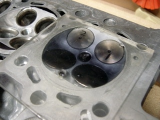
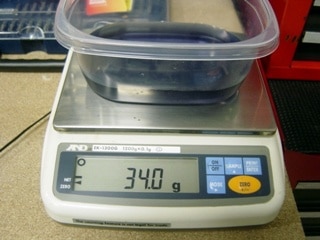
Measuring the combustion chamber volume of a BMW M54 cylinder head to verify compression ratio. This is also know as “CC’ing” a head. Rather then trying to measure to a high level of accuracy with graduated measuring cups or cylinders, we measure by weighing the displaced volume of liquid. Using this method we can achieve accuracies of plus or minus a tenth of a CC.
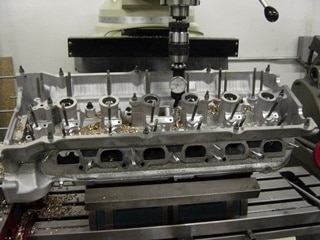
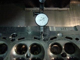
Indicating the center of a valve guide prior to drilling. There are many ways to remove worn valve guides but drilling them prior to pressing them out is the best way to prevent galling damage to the head’s valve guide bores. The head must be set up so that the drill bit is perfectly aligned axially to the guide bore. Drill diameter is selected to leave around .020″ of guide material after drilling. Once the guide has been drilled it can easily be removed without damaging the head.
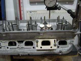
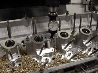
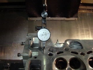
Checking head flatness (warp) on a CNC mill table with a dial indicator. The indicator is zeroed on one end of the head surface and swept across the entire head surface. This allows us to see exactly how much warp is in the head and where it is located. This head indicated zero at both ends and .002″ low in the middle, a very acceptable number.
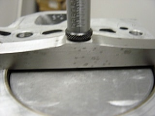
Here we are measuring piston deck height (distance of the piston deck above or below the cylinder deck surface) at TDC with a depth micrometer. This value is used in compression ratio calculations and squish clearance calculations.
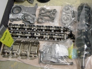
Here you also see engine parts being bagged and organized after coming out of the ultrasonic cleaner. Everything will be inspected and measured before going back into the engine.
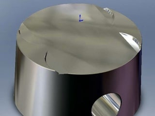
We created a CAD model of a custom piston we designed. This was a 11.5/1 flat top BMW M54 piston that we were having made by CP Pistons. The 3D modeling allows us to calculate the valve pocket displacements and verify all our calculations before having them made.
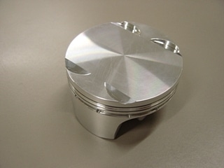
Also shown is the finished piston as received from CP Pistons.