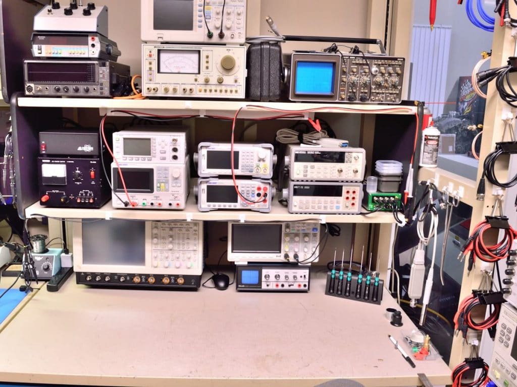
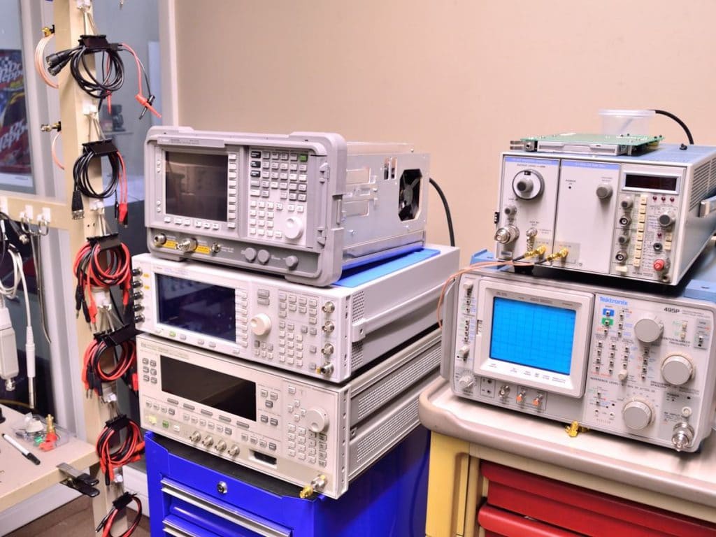
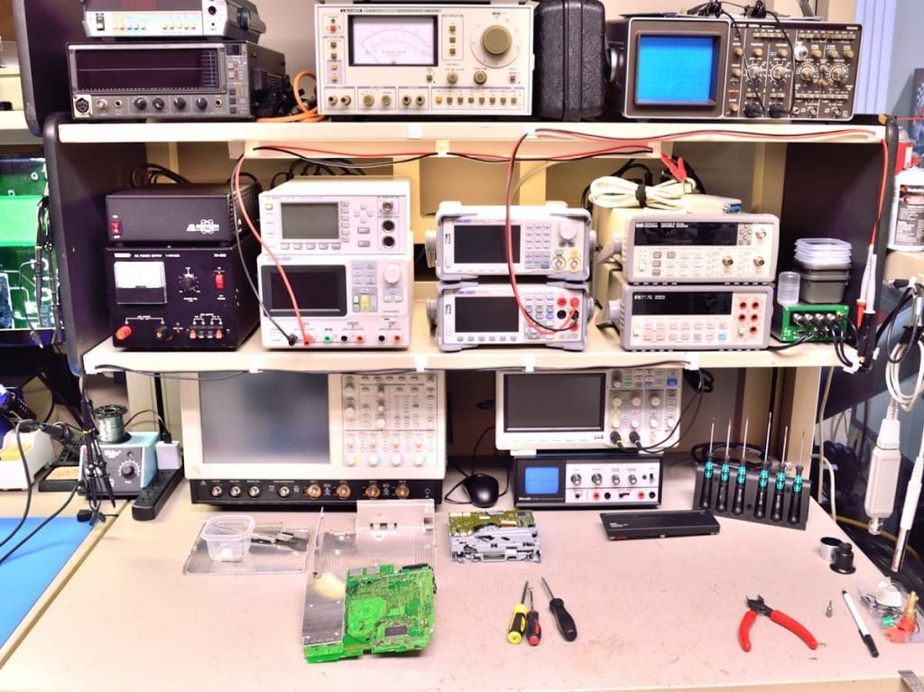
These images are from our main design, test and repair bench. We have some of the best analog and digital test equipment made from manufacturers like Hewlett Packard, Agilent, Tektronix and Phillips.
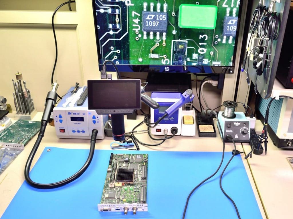
This is our surface mount components bench. We have all the proper gear for troubleshooting, de-soldering and soldering today’s micro size surface mount components. The small screen with the lens attached is a video microscope.
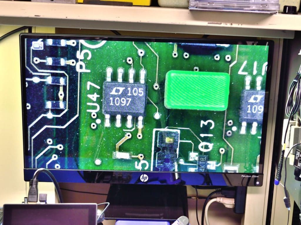
The video microscope is a necessity when working with small surface mount components. The integrated circuit with the number 1097 on it is actually less than a quarter of an inch long.
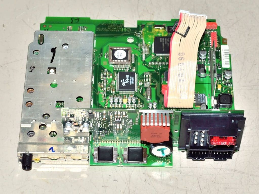
Here you see a disassembled BMW Tuner/Amplifier/CD unit in preparation for an audio amplifier repair/modification.
In the 2nd image you can see the two square, black, postage stamp size integrated circuits. These are the stock amplifier circuits. These are a high failure item and the solutions is to completely remove them from the circuit and install an entirely new circuit made of higher power dissipation components.
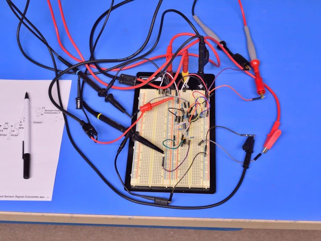
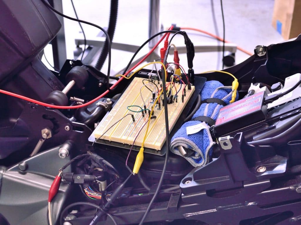
This is a breadboard prototype circuit being tested on the electronics bench. The circuit is for a BMW K1300GT motorcycle. We have installed a Dynojet Power Commander fuel injection mapping system on the bike, and would like to take advantage of the Power Commander’s ability to map fuel independently for each gear. Having individual maps for each gear allows for tuning for fuel mileage in 5th and 6th gear and acceleration in 1st thru 4th gears.
Unfortunately the the BMW’s wheel speed sensor does not output a signal that the Power Commander can read. To solve the problem we designed a circuit to modify the signal into something the Power Commander can deal with.
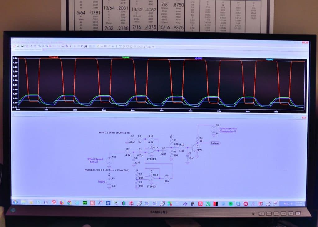
We start out by using electronic circuit simulation software to design the circuit and tweak in component values. You can define your power supply voltages, input signal type, frequency and amplitude, and your test conditions.
Once you’ve designed your circuit and assigned the component values on the bottom half of the screen, you can plot simulated output signals on the top half of the screen. Just click your mouse pointer on any node in the circuit diagram to see the simulated output at that point in the circuit.
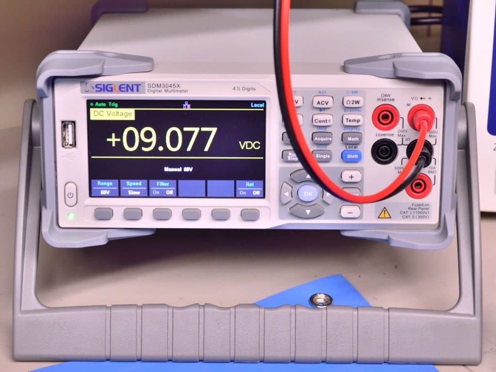
The test circuit needs 14.4 volts DC to replicate the voltage supplied by a running motorcycle, and 5 volts DC to replicate the voltage on the power commander wheel speed sensor input. Our bench power supply is set to provided these voltages.
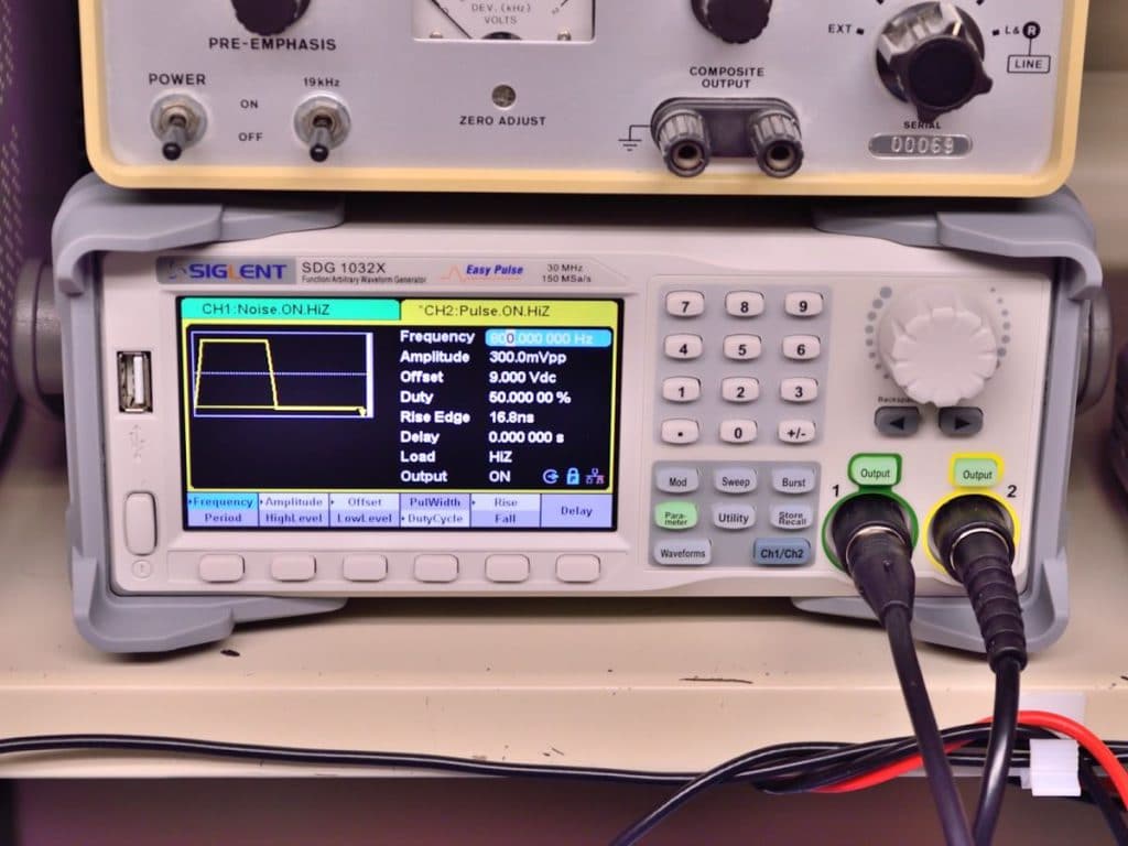
The signal generator is set to output signals that combine to replicate the signal we measured from the BMW’s wheel speed sensor. The signal consists of high frequency noise riding on top of a low voltage square wave.
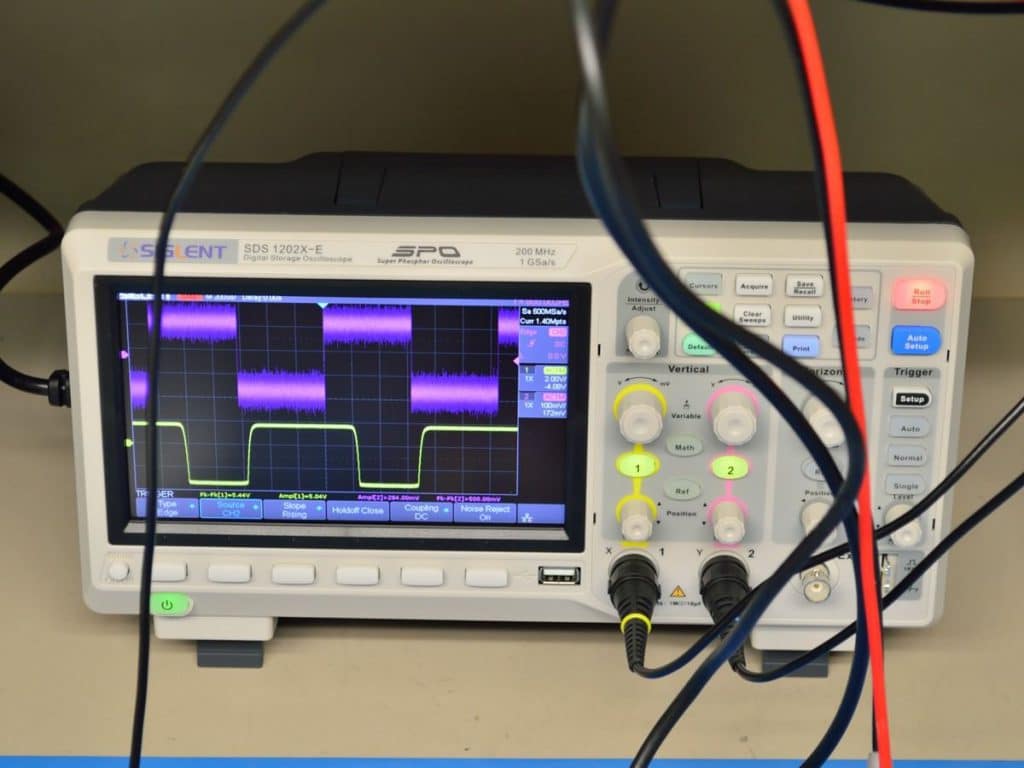
The top waveform is the generated noisy signal that replicates the bikes wheel speed sensor signal. The bottom waveform is the output of the prototype circuit. The output is a clean 5 volt square wave signal required by the Power Commander.
Here the prototype circuit is connected to the BMW K1300GT battery and wheel speed sensor and also to the Dynojet Power Commander.
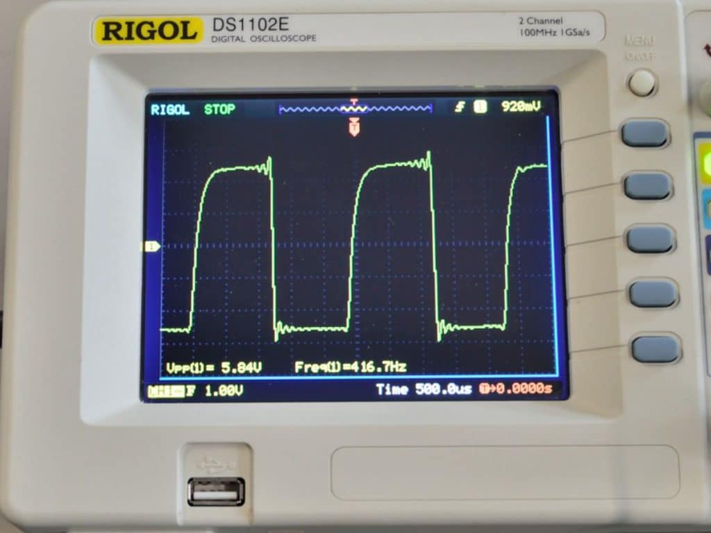
The scope shows the actual output of the prototype circuit with the bike running on the dyno. The circuit is working exactly as designed and simulated.
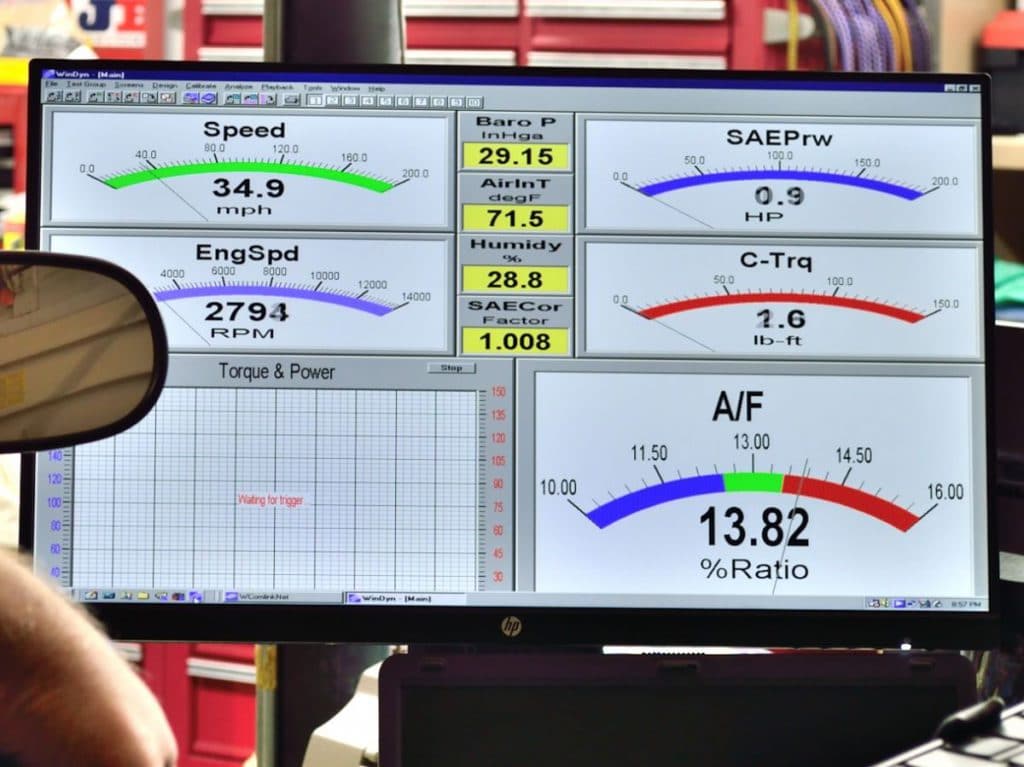
The dynamometer monitor shows that the bike is running at 35mph.
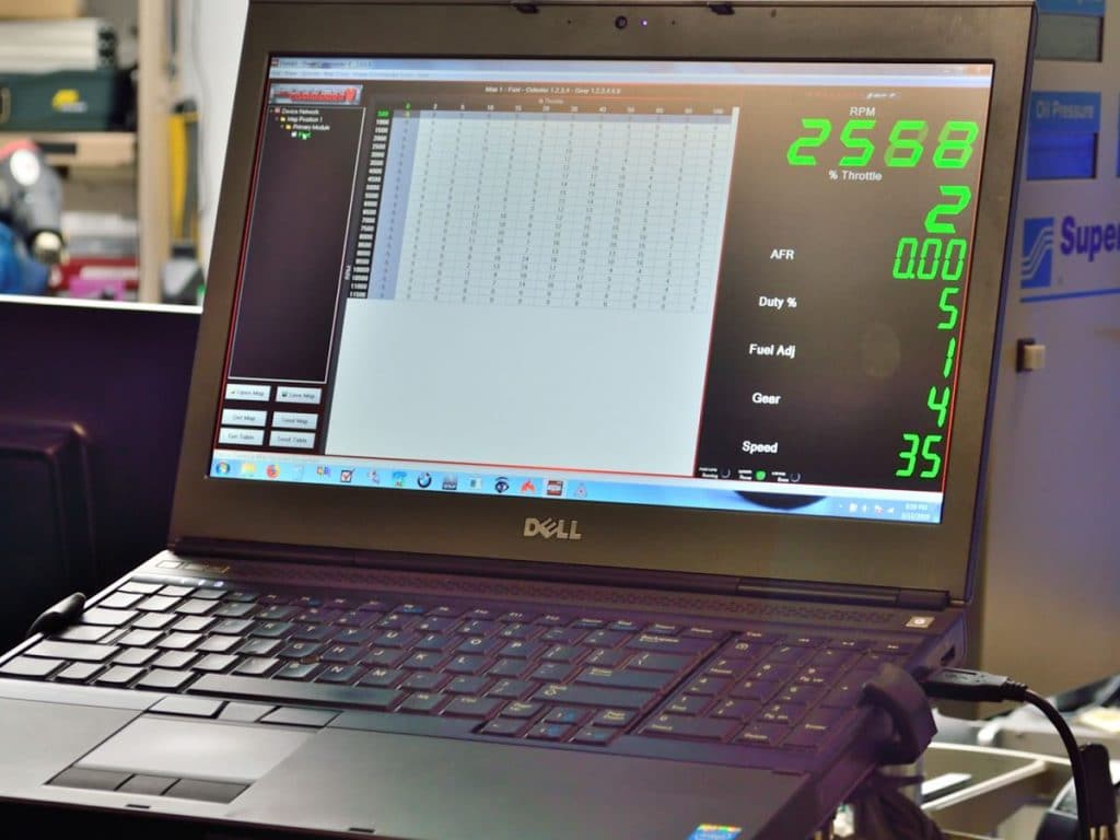
The laptop is connected to the Dynojet Power Commander V and it is correctly reading 35mph. Everything is working as it should.