BMW E60 M5 Connecting Rod Bearing Replacement Guide
Recommended parts replacement list with part numbers:
Part numbers listed are correct to the best of our knowledge at the time these instructions were written, we include them as a courtesy and we take no responsibility for their accuracy! This list does not include any parts that may be required to perform any tasks that are not directly a part of this procedure.
Required Part – Recommended Part – For reference if you decide to replace part – Notation
11-24-7-834-522 – OEM Connecting Rod Bolt – QTY = 20
11-36-7-834-573 – OEM High Pressure Hose (exterior) – Qty = 1 (see note 3 below)
Note 1 – Only required if you don’t want the trouble of applying thread lock to the old Bolts. Note 2 – Only required if you need to remove pickup tube for some reason. Note 3 – Only required if your anal.
****** IMPORTANT – IMPORTANT – IMPORTANT – IMPORTANT – IMPORTANT ******
This DIY guide is only recommend for people with a LOT of experience wrenching on cars and with access to a full compliment of professional quality tools. I HIGHLY recommend that you completely read through the entire instructions several times before you begin, to familiarize yourself with procedure. If you don’t feel comfortable with any part of these instructions please do not attempt this project on your own.
If you cannot have a computer nearby during this procedure, print off these PDF instructions. I highly recommend using a laptop computer at the vehicle location if available over using the printed PDF instructions. The ability to enlarge the pictures on a computer display will ensure that all the important detail information in the pictures will be visible.
DO NOT attempt to perform these instructions using a Smart Phone! The pictures contain important details that would be very difficult to view properly on the small display of a smart phone.
Make sure that you read each step fully from beginning to end before you perform any part of a step. Some steps contain multiple procedures, and some steps contain information at the end of the step, that is crucial to completing the step properly.
This DIY is a little different from my normal instructional format. Usually my DIY guides are written with an extreme amount of detail everywhere, such that anyone with basic mechanical skills would have no trouble completing the procedure. Since this DIY is intended for people with a more advanced level of mechanical experience, I will not describe every aspect of the procedure in detail. I am assuming that anyone attempting this procedure will know how to drop the under body panels, remove spark plugs, intake plenum, etc. Detail will be provided where needed, but you will be on your own for some of the basic tasks.
Based on the intended user of this DIY, the question is how much detail to provide. When it comes to items such as oil pump internals, rod bearing installation, connecting rod prep, the proper use of a test indicator, etc, I will have to assume that some of you may not have experience in all of these areas and will appreciate a lot of detail for these steps. If I have supplied too much detail for some of you, please understand that I am not “talking down” to anyone. I just want to make sure that there is enough detail for someone you has never been inside a motor to successfully perform this procedure.
The starting point for this procedure is with the engine oil drained, underbody panels and intake plenum removed, and vehicle on a lift. While I am aware that people have successfully completed this job with the car on engine stands, I really don’t recommend it.
Click on images in the instructions to view full size
#1
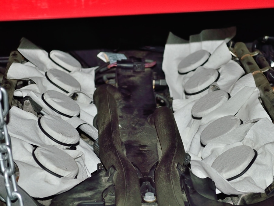
Make sure that you cover the openings to the throttle bodies with something. If not, you can guarantee that something will end up falling into one of them.
Here I used paper shop towels with o-rings to hold them in place.
#2
Remove all spark plugs and cover the openings with something. You should do this before installing the engine support.
I just forgot to take a picture until after I had installed the support.
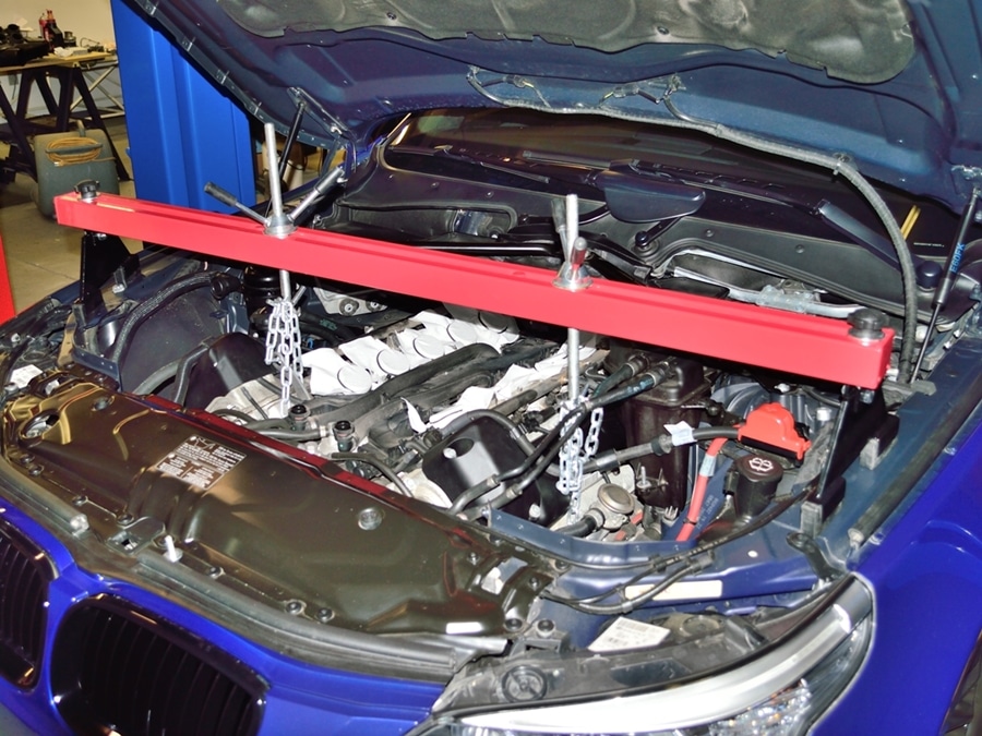
#3
Install an engine support. This is a Harbor Freight unit and is actually quite nice.
I found an unused threaded hole on the front drivers side of the cylinder head. I bolted the second chain to it with fender washers on each side of one of the chains links. This way I did not need to use a second engine support on the rear engine lifting loop.
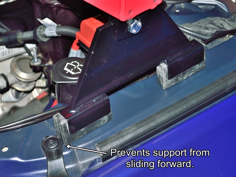
#4
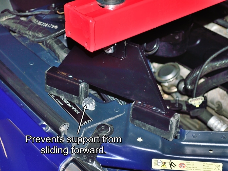
I positioned the support like this on the passenger side to prevent the support from wanting to slide forward.
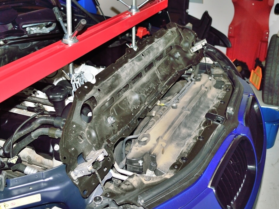
After you have removed the under body covers remove the chassis brace.
#8
Cover removed and ready to start the major disassembly.
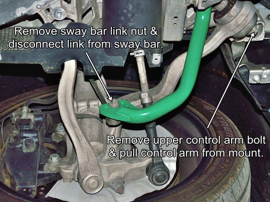
Remove both front wheels before proceeding to disconnecting suspension members. You will notice from the following pictures that I wasn’t smart enough to do it until later.
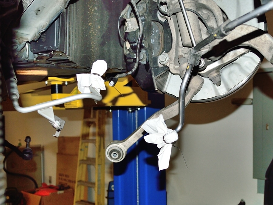
#9
Disconnect the sway bar link from the the sway bar on both sides.
Remove the through bolt that attaches the upper control arm to the sub frame and pull the control arm down and out of the way. Repeat on the other side of the vehicle.
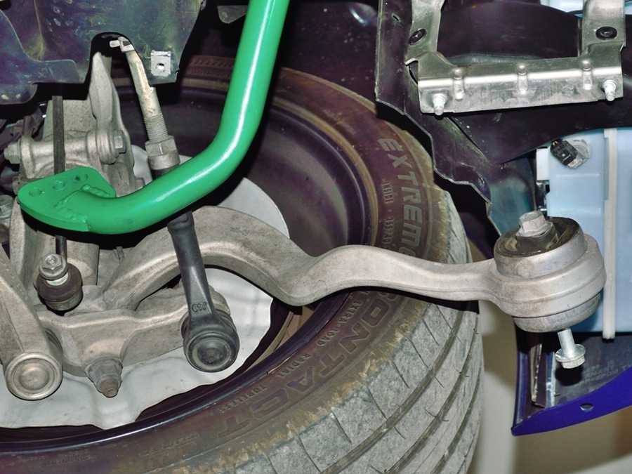
#10
Whenever possible I like to reinstall any removed hardware onto the removed item in the direction that the hardware was removed. That way there is no confusion about what hardware goes where and how it needs to be oriented during reassembly.
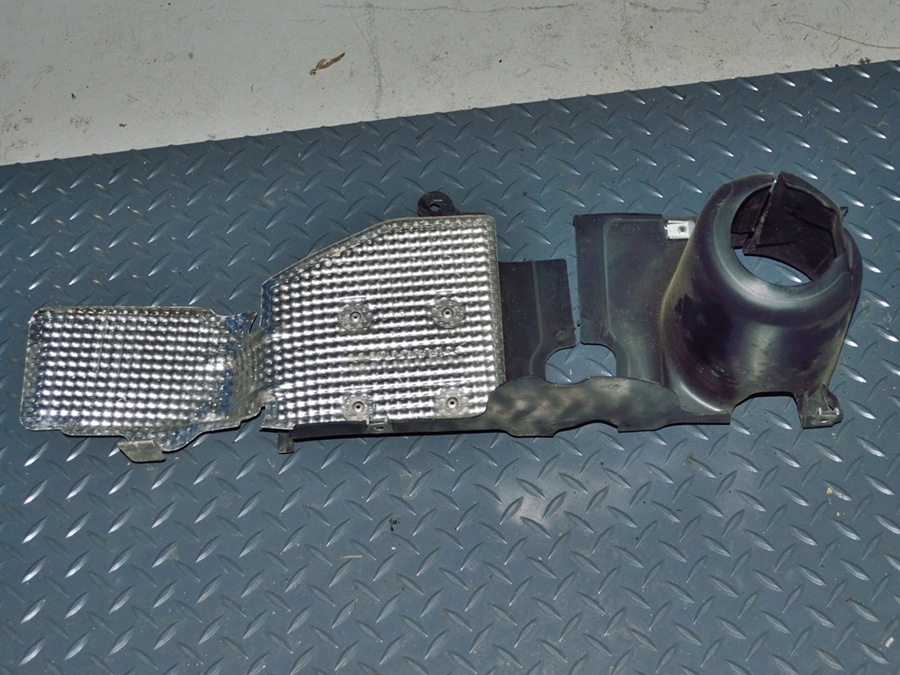
#11
Remove the steering rack tie rod covers from both ends of the rack.
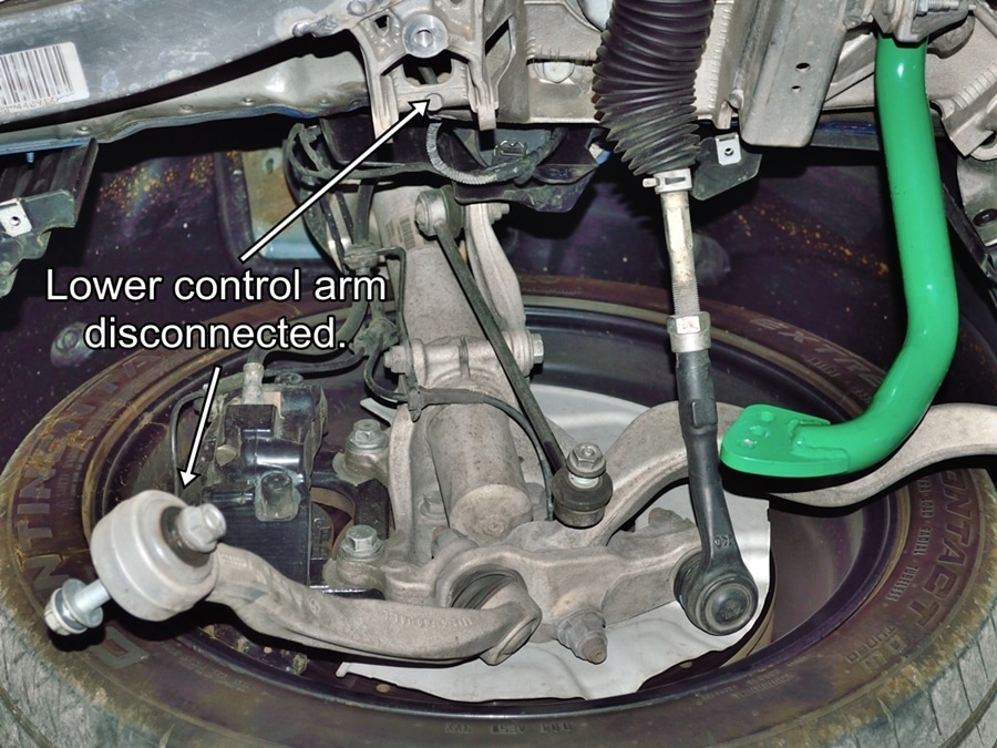
#12
Disconnect both lower control arms from the sub frame.
On the drivers side you also need to disconnect the suspension position encoder.
#13
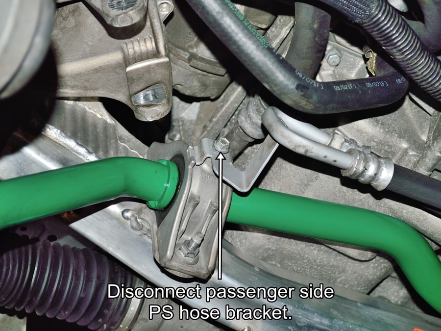
Disconnect the passenger side power steering hose bracket.
#14
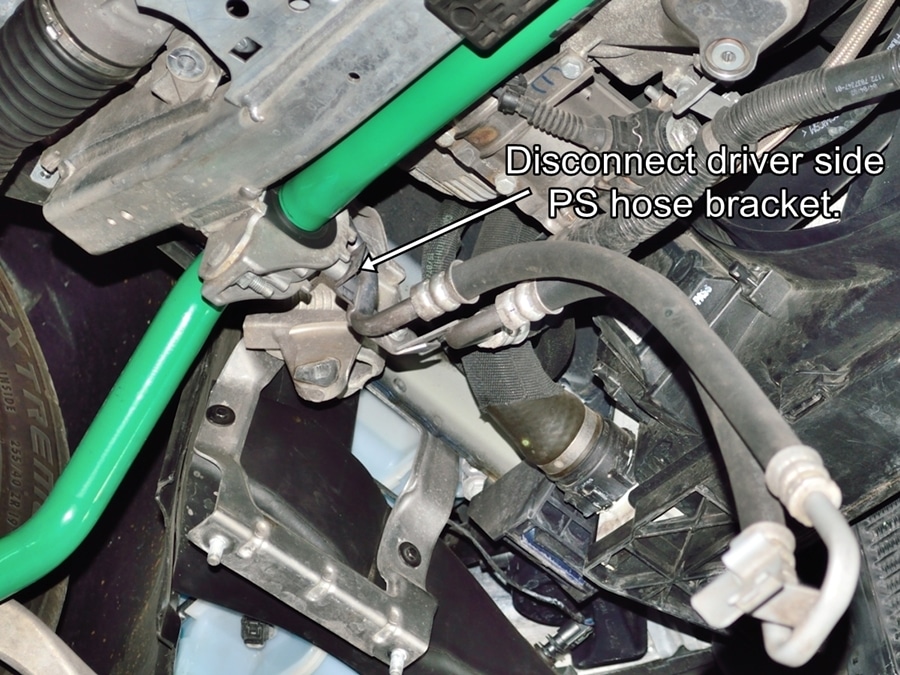
And the drivers side.
#15
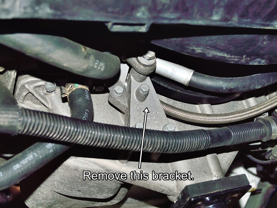
Remove the belt tensioner support bracket.
#16
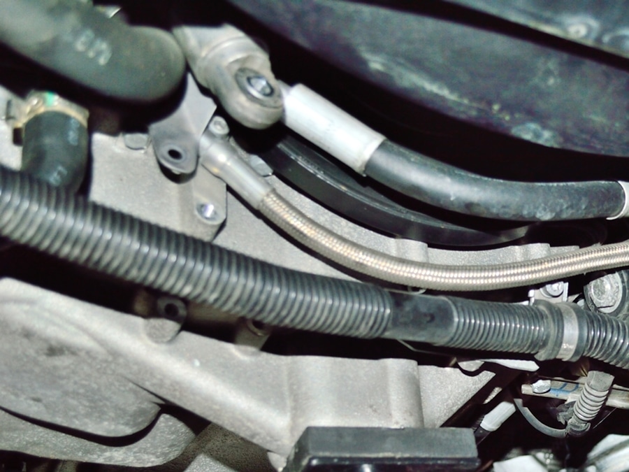
No more bracket.
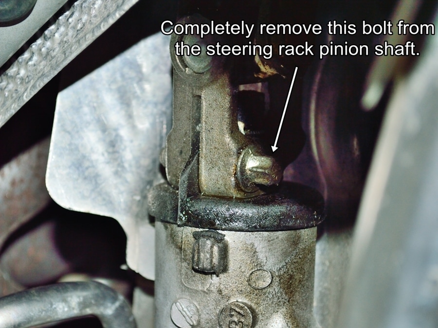
#17
Remove the bolt securing the steering shaft to steering rack pinion shaft. The bolt has to be completely removed to pull the steering shaft free, not just loosened.
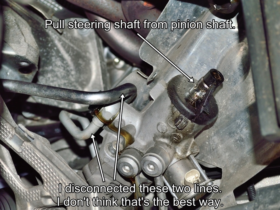
#18
Pull the steering shaft off from the pinion shaft.
I disconnected the power steering hydraulic lines here, but doing it that way ended up making them very hard to get back on.
#19
Find some way to cover the disconnected hydraulic lines. I used shop paper towels and twist ties.
#20
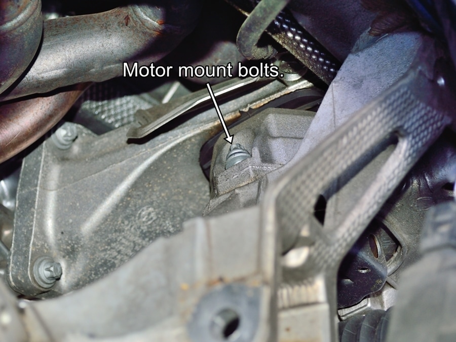
Lastly you need to remove the motor mount bolts. When I first looked at this it didn’t appear that the main motor mount bolts were accessible from above through the engine compartment, so I removed these four bolts from below with a gear wrench. They weren’t to hard to get to, but they were difficult to line up when reinstalling the sub frame.
I suggest you remove the two main bolts from above.
#21
That should be everything that needs to be disconnected to drop the sub frame. Start by slightly loosening the six bolts securing the sub frame to the vehicle. Once they are all loosened remove the four bolts from the outer corners but leave the two bolts closest to the middle in place.
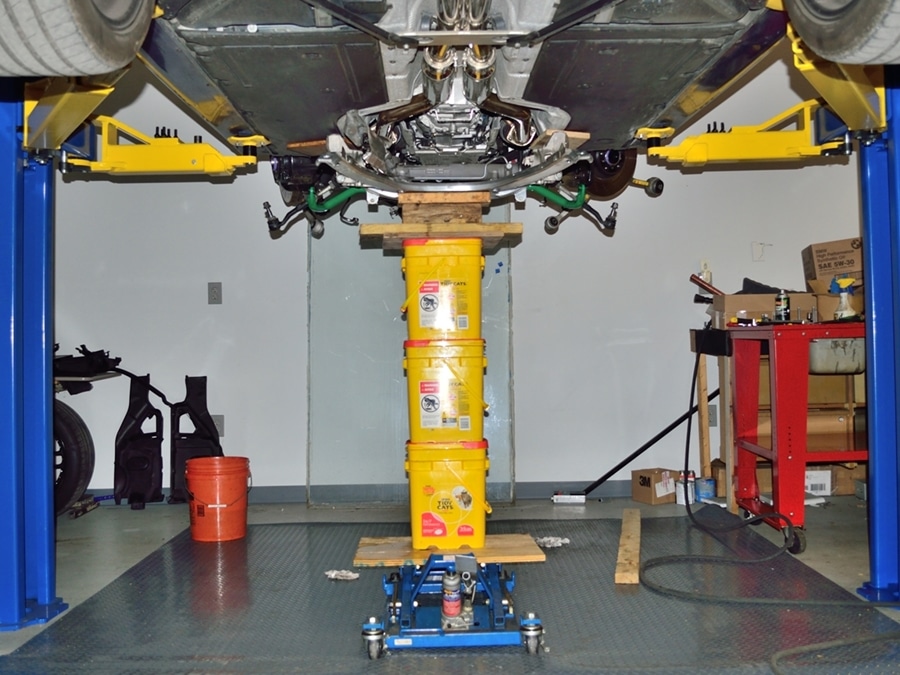
If you have two people, remove the last two bolts while supporting the sub frame from both sides, then lower sub frame and steering rack out of the way.
If you only have one person, as you can see from the picture, you will need a platform motorcycle jack, three jumbo cat litter containers and various pieces of lumber.
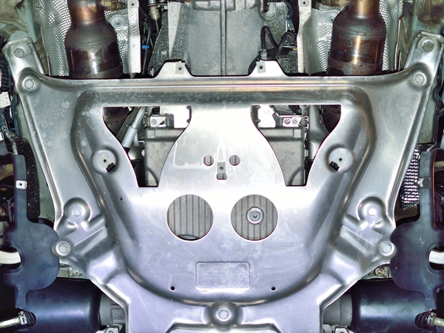
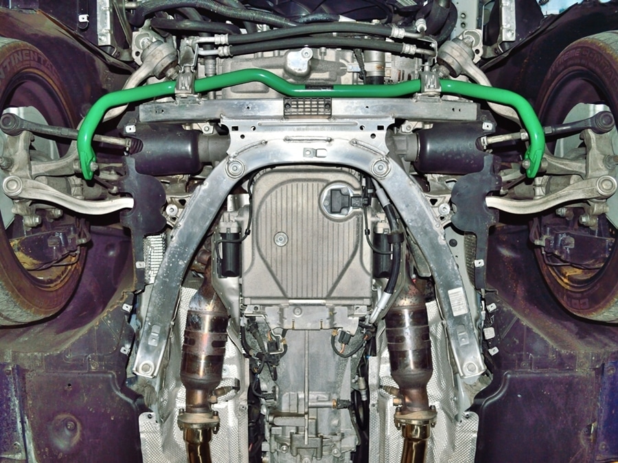
#22
View with sub frame removed.
#23
This is a good time to wipe clean anything that could cause dirt or debris to get into the engine during disassembly or reassembly.
It’s a good idea to thoroughly clean the perimeter of the oil pan along the crankcase to oil pan parting line.
#24
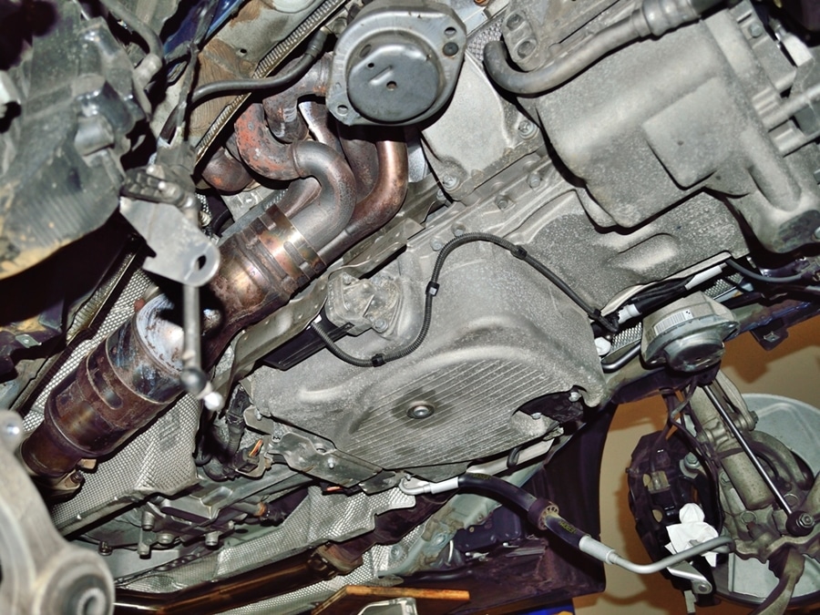
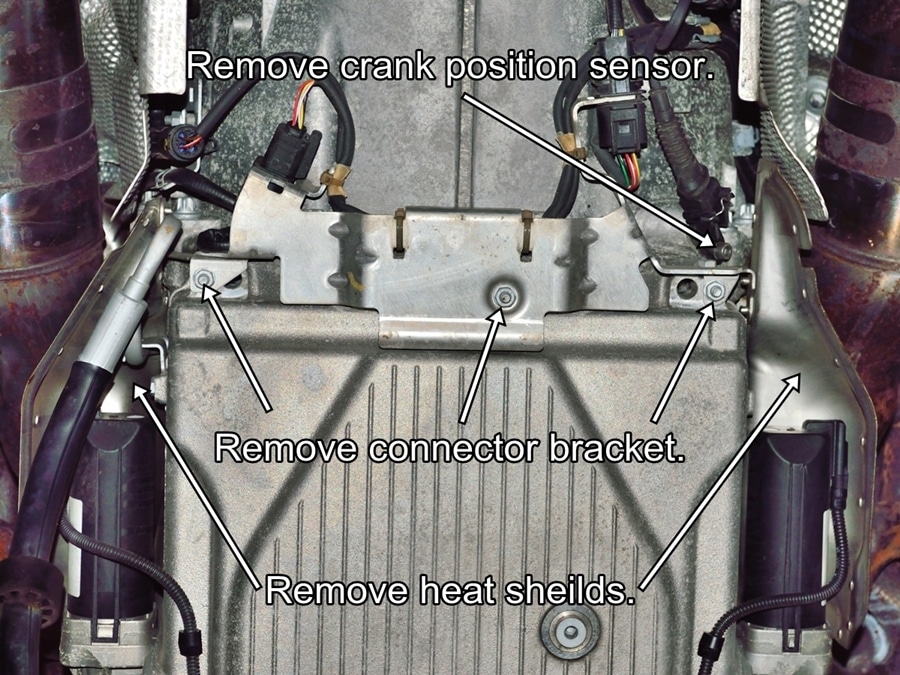
Remove the connector bracket and heat shields shown.
You also have to remove the cam position sensor for access to one of the lower bell housing bolts.
#25
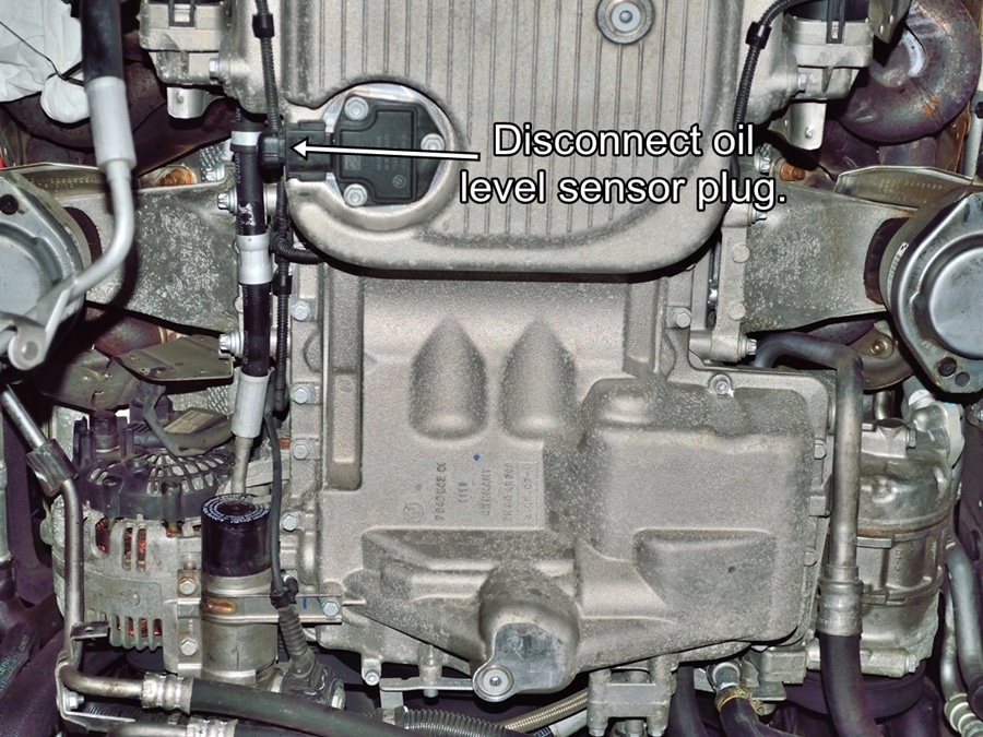
Disconnect oil level sensor plug.
#26
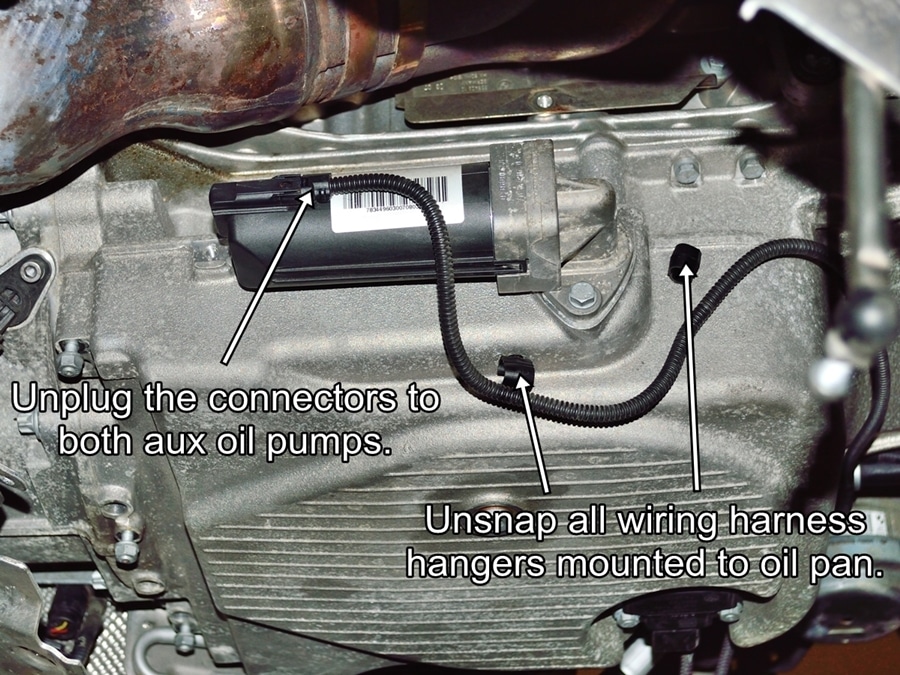
Unplug both aux oil pump connectors. Snap open all wiring hangers to free wiring harness.
#27
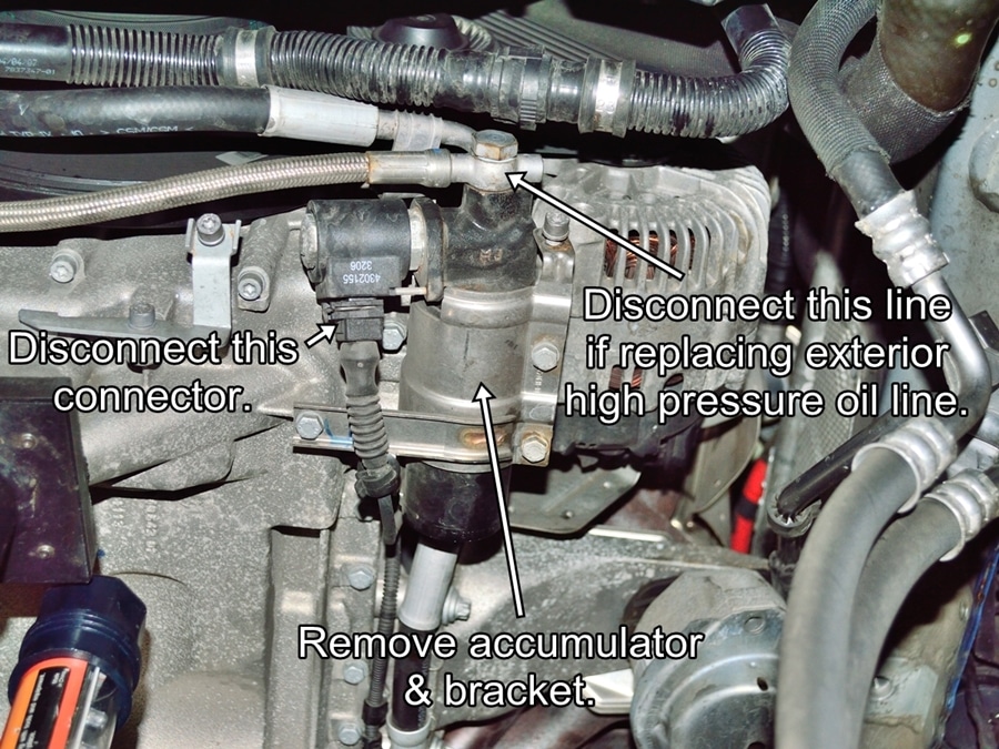
Unplug the electrical connector from the accumulator. If you are not replacing the external VANOS high pressure line you can leave it connected to the accumulator. Unbolt the accumulator from the oil pan, and let the accumulator hang from the oil line.
If you are replacing the external high pressure line, disconnect the line from the accumulator before removing the accumulator.
#28
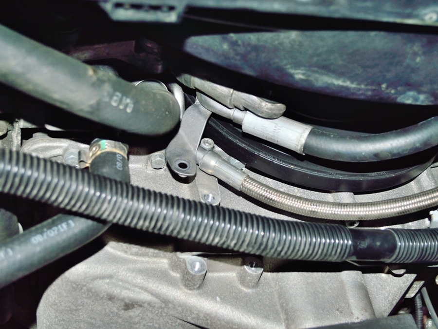
Remove hose bracket bolt.
#29
Assuming that you already drained the oil, crack loose all of the oil pan bolts. Remove all but two bolts on opposite sides around the mid point of the pan. Support the pan while removing the last two bolts then drop the pan.
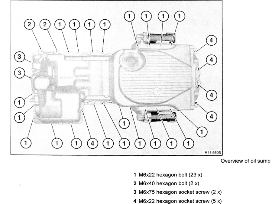
Don’t miss the four bolts securing the transmission bell housing to the rear of the oil pan or the four recessed torx bolts at the far rear of the oil pan next to the transmission bell housing (#4 on diagram). If you don’t have a torx driver that fits into the recess, they will come out with an extended reach allen driver.
#30
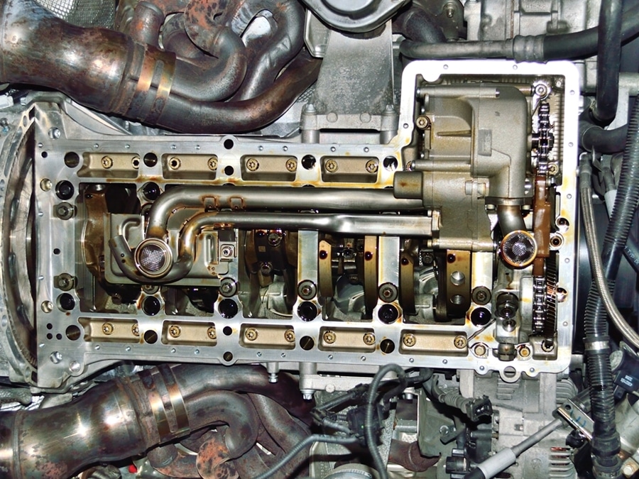
Ready to start the good stuff.
#31
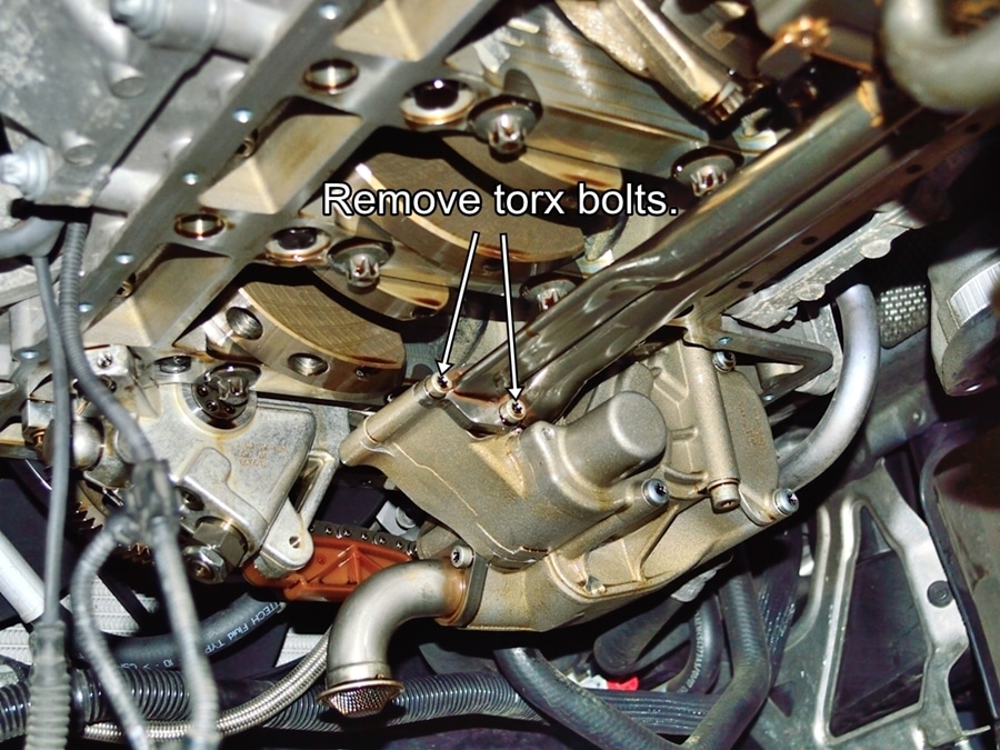
Remove the two torx head bolts securing the oil pickup tubes to the oil pump
#32
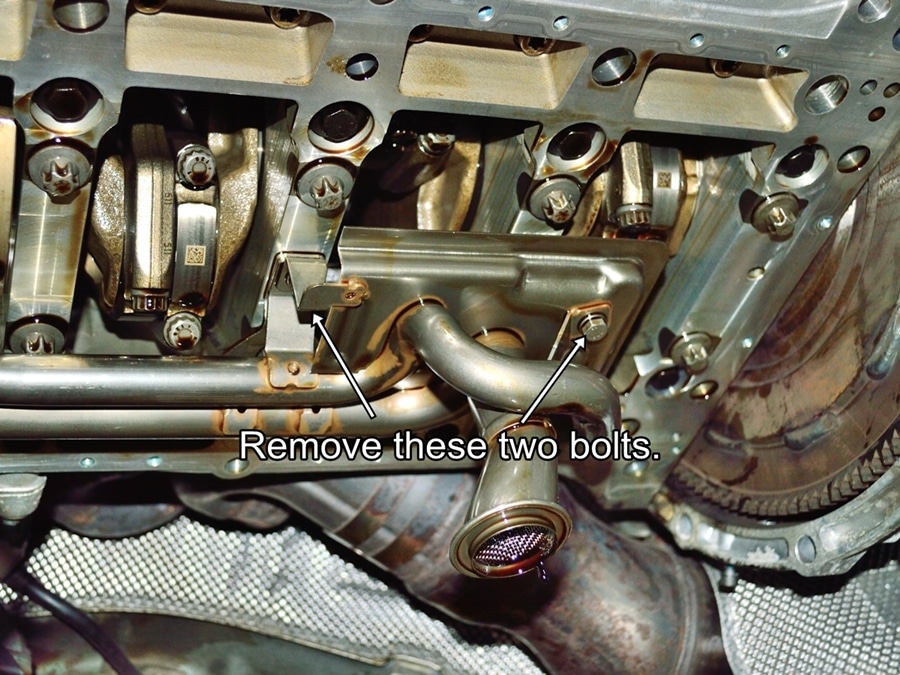
Remove the two bolts holding the oil pickup bracket to engine, then slide the oil pickup assembly away from the oil pump to remove.
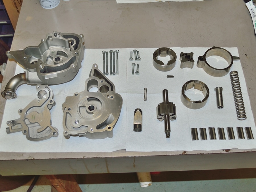
The next steps refer to removing the oil pumps. Removing the pumps is not necessary if you are not replacing either of the pumps or the high pressure VANOS oil line. I recommend removing them anyway for inspection. If you do not wish to remove the pumps you can skip to step #52.
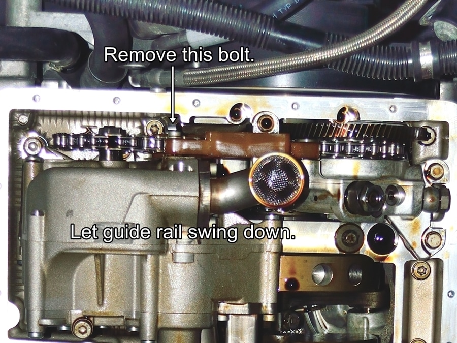
#33
Remove the bolt shown in the picture from the chain guide rail and let it pivot downward and out of the way.
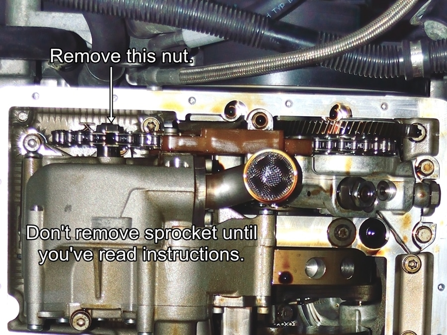
#34
Note: This picture has not been updated by previous step.
Remove the nut from the main oil pump sprocket. While making sure the chain tensioner shoe does not drop downward, remove the sprocket from the oil pump shaft.
Carefully pivot the tensioner shoe downward to remove the tensioner piston, base washer and spring.
Do not let the piston, washer and spring fall out as you lower the tensioner shoe. Make sure that you recover all three pieces.
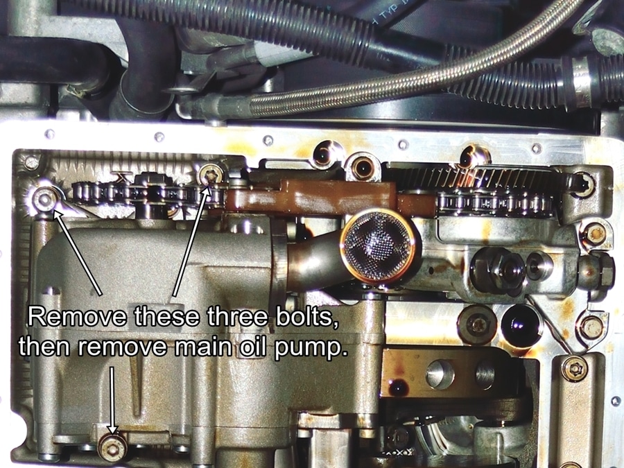
#35
Note: This picture has not been updated by previous steps.
Remove the bolts shown and remove the main oil pump.
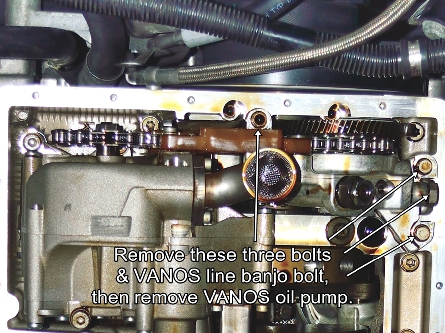
#36
Note: This picture has not been updated by previous steps.
Remove the bolts shown and remove the VANOS high pressure oil pump and chain. Discard the copper sealing washers and use new washers when reinstalling.
The next section of instructions refer to disassembling the main and VANOS oil pumps. Take your time and take pictures or make notes during disassembly to make sure that everything can be put back together exactly as it came apart.
#37
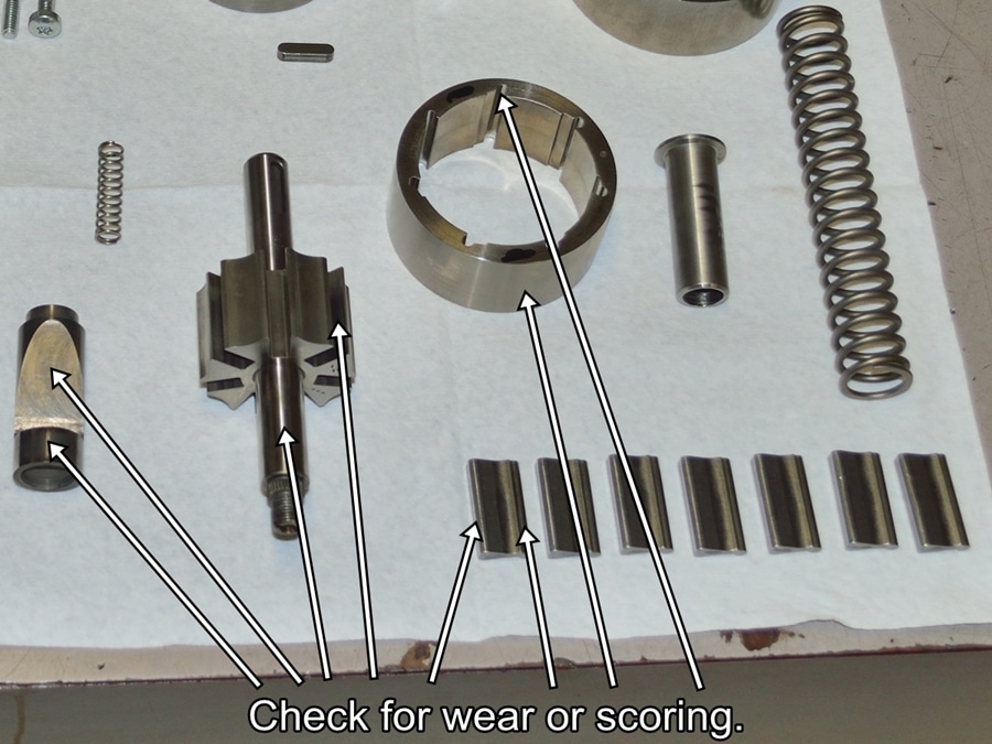
If you wish to inspect the main oil pump for wear follow the next 7 steps.
Carefully disassemble the main oil pump making note of how each bolt and part are oriented to ensure proper reassembly. I marked the outside faces of any parts that could go in two ways with a Sharpie. I kept the oil pump vanes in order and marked the starting slot on the rotor.
After thoroughly cleaning with brake cleaner, completely inspect all parts for signs of wear galling or heat discoloration.
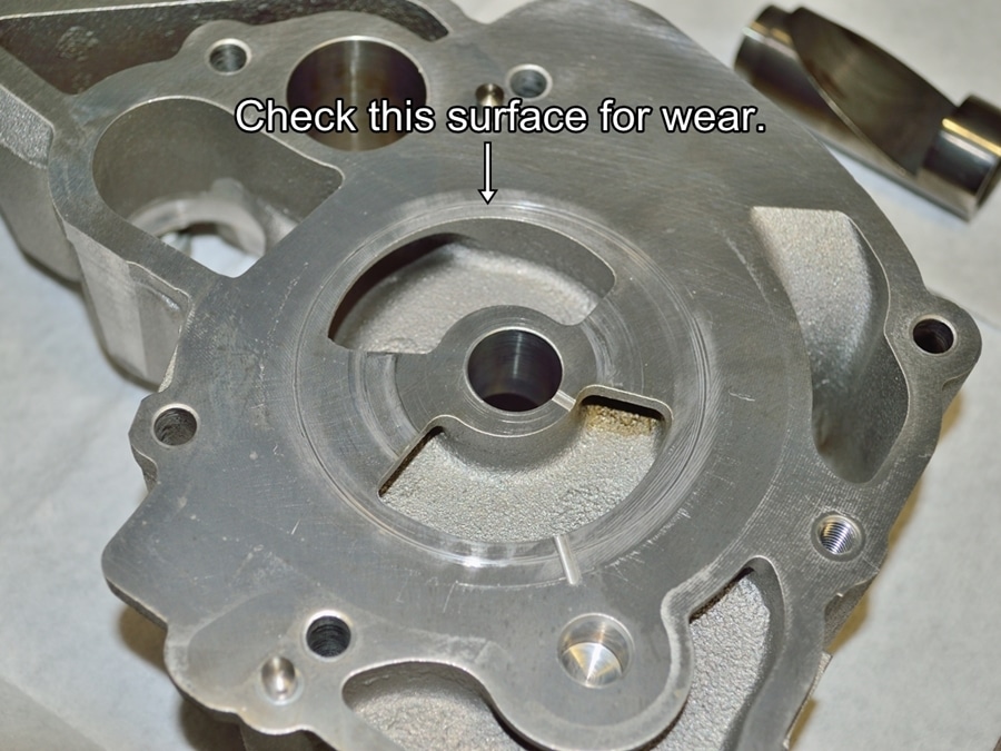
#38
Check pump cover surface for scouring. What looks like scour marks in this picture are just polish marks. If you can’t feel the marks or catch a finger nail on them they are OK.
#39
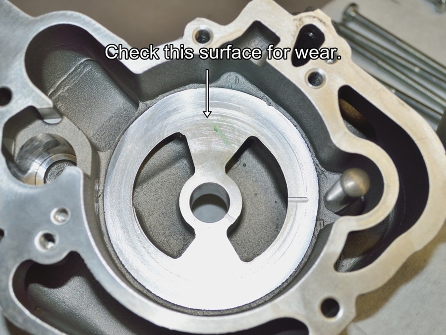
Check the pump body in the same way.
#40
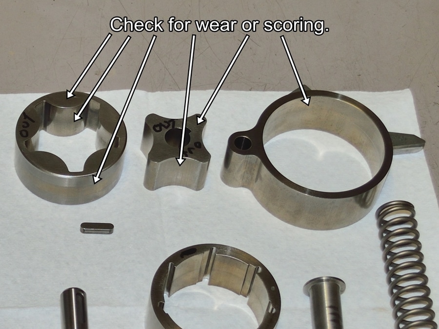
Check all internal parts as well.
These are the scavenge (or transfer) pump internals. This is the pump that transfers oil from the small front sump to the main rear sump.
#41
And the main variable volume pump which supplies the VANOS high pressure pump and all other engine internals.
Check all parts as you did with the scavenge pump.
#42
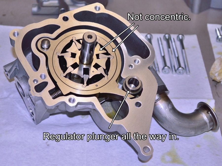
Main pump internals reinstalled in clean and dry state for illustrative purposes only. All parts should be fully oiled during final pump assembly.
Note the position of the volume regulating plunger. At minimum oil pressure the main spring pushes the plunger inward which moves the pump internals to the maximum eccentric position shown here.
In this position the pump outputs the maximum volume of oil.
#43
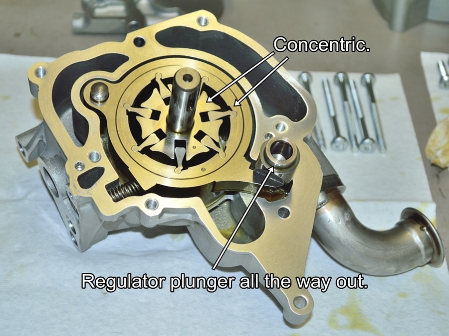
As oil pressure increases, the oil pressure counteracts the spring tension and moves the plunger outward, which reduces the volume of oil being pumped. You can see in this picture that with the plunger in its fully outward position, the inner rotor is concentric to the outer rotor, which results in no oil being pumped.
The pump regulates oil pressure by varying the volume of oil supplied. If the engine needs more oil volume, the pressure will drop, causing the plunger to move inward, which causes the pump to supply more volume, which increases the pressure.
If all pump parts are determined to be in very good to excellent condition you can reassemble the pump.
Make sure that all parts are completely clean before beginning reassembly. Thoroughly oil every part and dump your motor oil of choice into every cavity of the pump during reassembly.
Set oiled pump aside until you have finished the rod bearing replacement. I typically put all cleaned and oiled parts that are waiting for reinstallation into jumbo zip lock bags to keep them clean.
Even if you didn’t disassemble and inspect the main oil pump, I would highly recommend doing the VANOS high pressure pump.
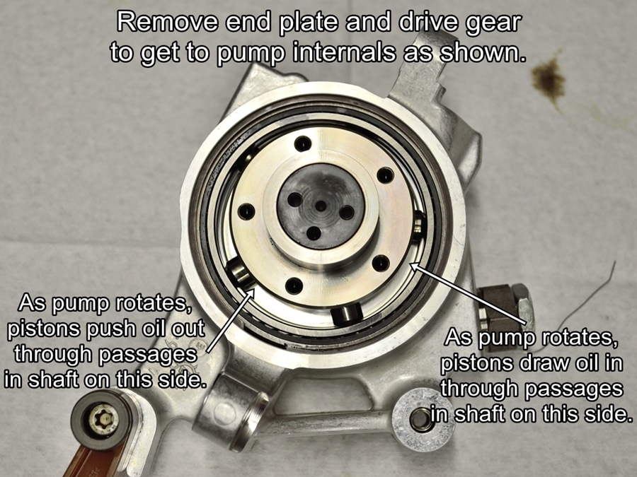
#44
Remove the end plate and drive gears from the VANOS pump to get to this point.
Because the pump rotor is positioned non-concentrically within the pump housing, as the pump internals rotate, one half of the pistons will be moving outward in their bores and the other half will be moving inward. The pistons moving outward are filled with oil through passages in the center shaft which are supplied with oil by the main oil pump.
The pistons being forced inward, pump that oil through another set of passages and out to the VANOS solenoids. This seems to be a very simple and efficient design.
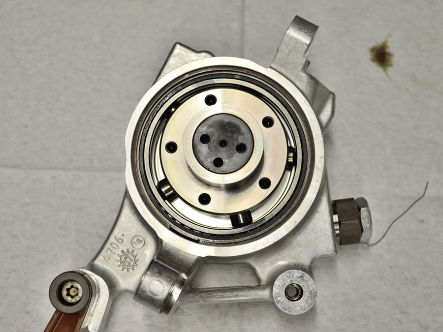
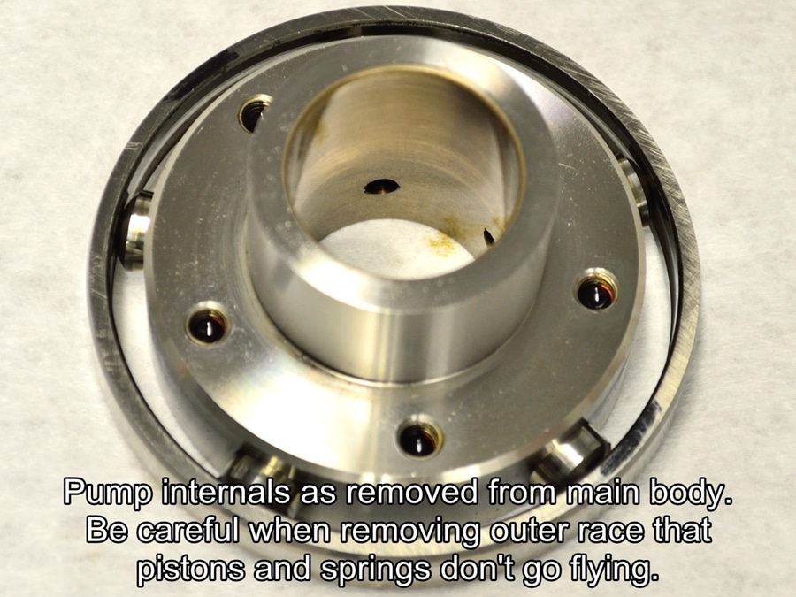
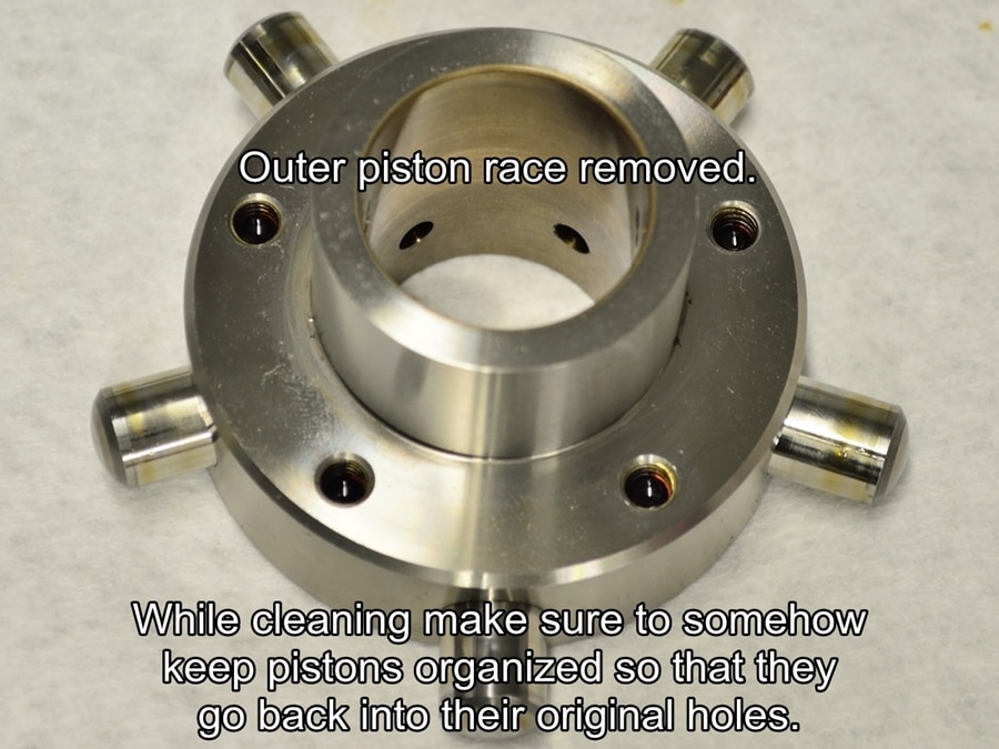
#45
At this point the pump internals can be lifted straight up and out of the pump body. Be very careful that the outer race does not fall off while removing the pumps inner assembly.
If the outer race comes off it will allow the spring loaded pistons and springs to pop out. Ideally you will want to keep the pistons in their original bores when reassembling.
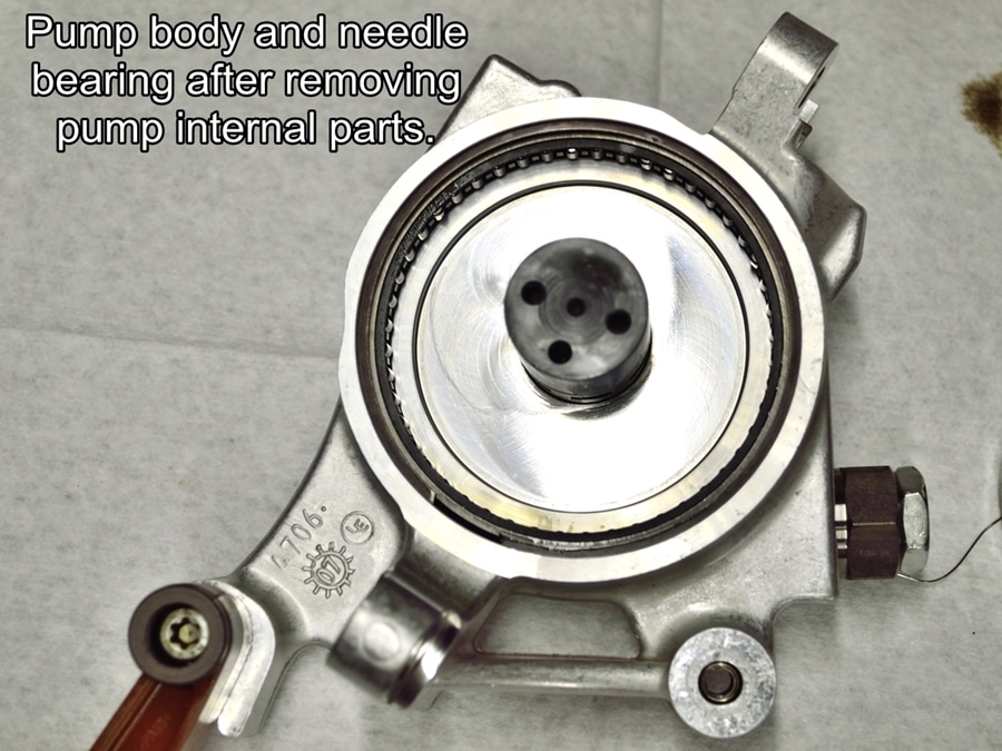
#46
Once the inner pump assembly is removed from the body, thoroughly clean the main pump body and needle bearing with brake parts cleaner.
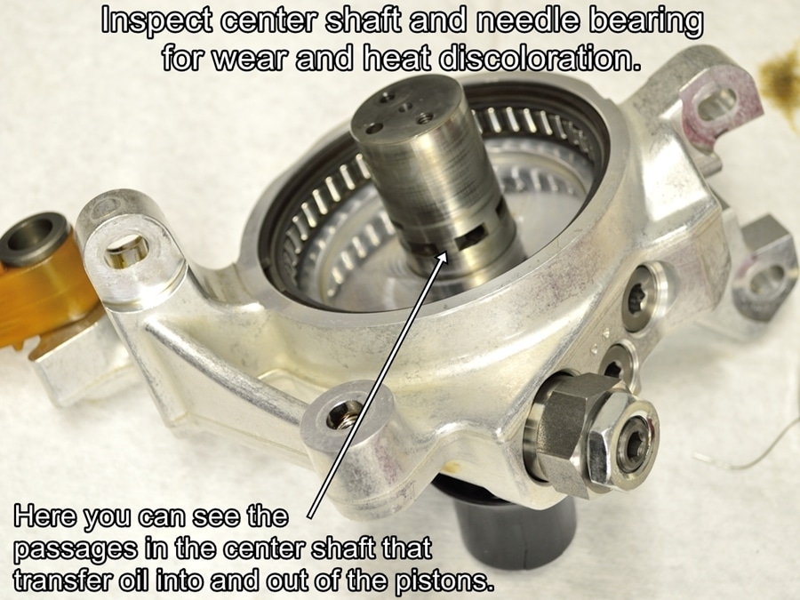
#47
Once clean, closely inspect the center shaft and bearing needles for any sign of wear, galling or blue heat discoloration.
If anything does not appear to be in very good to excellent condition, I would suggest replacing the pump.
#48
Now you can carefully slide the outer race off of the pistons. The pistons have springs behind them and can shoot out a little ways if not constrained. Just wrap your palm around one side of the assembly then slowly lift up on the side of the race where your palm is. Your palm will keep the pistons from coming out of their bores as you remove the race.
It’s OK if the pistons come out of bores for cleaning and inspection as long as you find a way to ensure that they go back into their original bores.
#49
Thoroughly clean all pump parts with brake parts cleaner.
#50
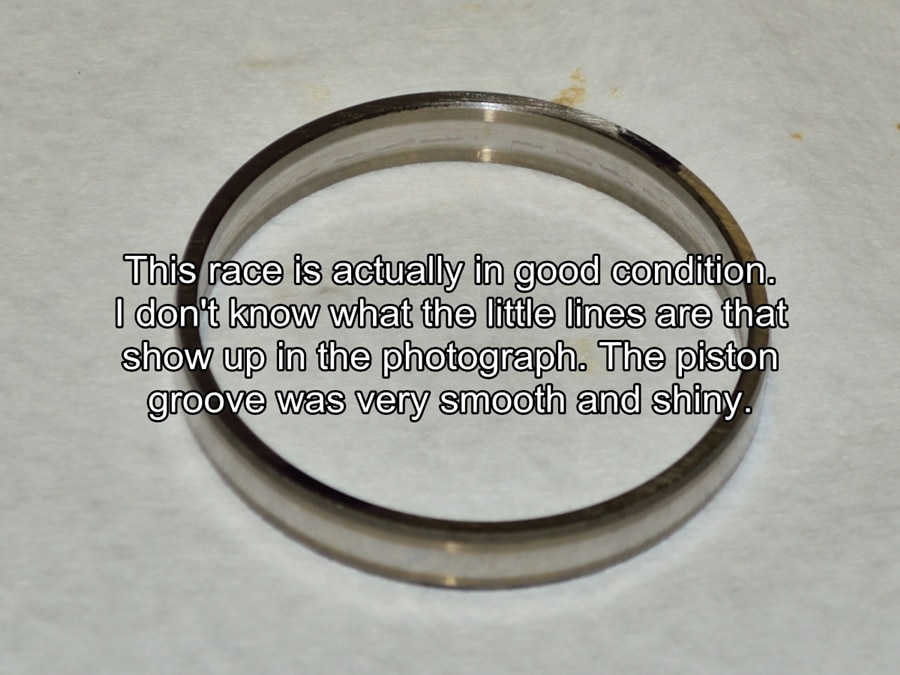
Once clean, carefully inspect the inside and outside of the pump race for any signs of wear, galling or blue heat discoloration.
#51
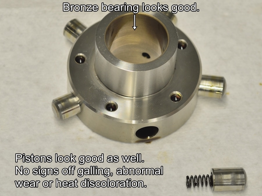
Carefully inspect the pump rotors bronze inner bearing and the pump pistons for any signs of wear, galling or blue heat discoloration.
#52
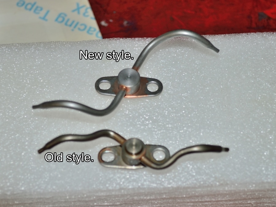
Shown here is the difference between the new and old style piston oil squirters. These can be replaced with the engine in the vehicle before or after replacing the rod bearings.
To install the new style squirters you need to put one of the allen screws onto a long allen driver, put the new squirter onto the screw shank, then carefully raise everything into place and start the screw into its hole. It takes some patience but it is very doable. Once you have the first screw started, tighten it just enough to properly position the squirter, install the second screw, then tighten both. I used a drop of blue thread lock on these.
If you are going to replace the VANOS high pressure oil line, this is a good time to do it. Installing the new line is a tight fit but just take your time and you will get it.
Here is a link to the BMW TIS VANOS HP line replacement instructions. You will need to remove a few things from the front of the engine, but nothing that I think requires special instructions. TIS states to remove the right side coolant hose, I did not do that and I had no trouble getting access to everything I needed to.
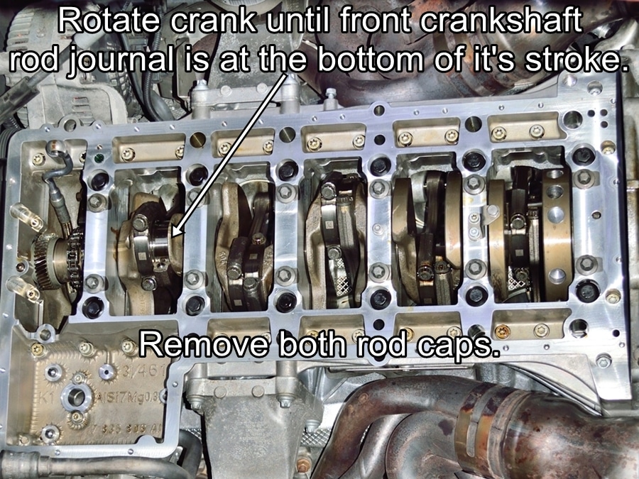
It’s now time to start the bearing replacement. I started at the front of the engine and installed the new bearings one crank throw at a time while working my way to the rear of the engine. I waited until all the new bearings were installed to torque the rod cap bolts.
Always try to rotate the crankshaft in it’s normal direction of rotation, which if clockwise as facing the front of the engine. Since there is very little tension on the cam chain tensioner without oil pressure, there is a slight risk of the cam chain jumping a tooth if the crankshaft is rotated backward.
Rotate the crank clockwise until the crank throw for the front two rods is facing downward. Remove the two rod caps from the crank throw you are working on. Make sure that you mark them somehow to ensure that they go back on the same connecting rods they were removed from.
A word of caution is in order regarding working with “cracked” mating surface connecting rods. Be VERY careful to not bump the cracked surface of the rod cap against anything remotely hard. The cracked surfaces of the rod and cap consist of many tiny peaks and valleys which must mate to each other again perfectly when reassembled. While connecting rods are strong, they are not terribly hard. If you bump the cracked surface of the cap against something you run the risk of slightly flattening one of the little peaks. If that happens the cap will never fully seat properly onto the connecting rod again.
#53
Once both caps have been removed, using both thumbs on the bottom of the connecting rods, push each of them up far enough to completely clear the crank journal. Be careful not to scratch the journal with the bottom of the rod.
I rinse the bottoms of the connecting rods with brake parts cleaner to clean the bearing area and cap mating surfaces. Do not over spray to the point that you rinse the oil off of the cylinder walls.
#54
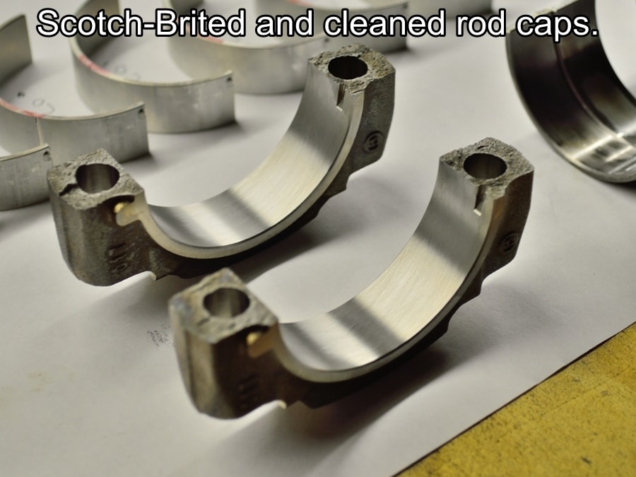
I clean the bearing surface of the rod caps with a piece of Scotch-Brite moistened with WD40. This will remove anything that may have transferred to the cap from the back side of the bearing shell but will not altering any dimensions. Make sure to thoroughly rinse the caps off with brake parts cleaner when finished.
You can carefully perform the same procedure on the big end of the connecting rods. You will need a finger size chunk of Scotch-Brite and a lot of care because of the limited space around the crankshaft journal. Again, make sure to THOROUGHLY rinse down the bottom of the rods and crank journal when finished.
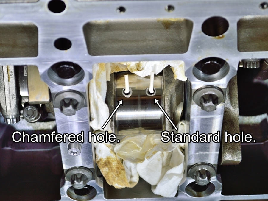
I’m not sure whether I should have included this next section or not.
Because of the rod bearing failure issues associated with the S85 engine I decided to slightly chamfer the trailing edges of the oiling holes. Don’t even think about attempting this unless you have a lot of experience doing fine detail work with a pencil grinder. If you decide to do this, proceed at your own risk of slipping and damaging the journal.
BTW – I’m not making any claims that this will help the bearing issues, it’s just fairly common practice when prepping high performance crankshafts. I helps to guarantee adequate oil flow to the rod bearing.
#55
What you see sticking out of the oiling holes are the bent upward stems of cut in half Q-tips. Also notice the paper shop towels packed around the crank journal. The cotton ends of the Q-tips prevent any metal dust from traveling up the oiling holes. The bent stems allow access to grind on the opposite side of the hole.
I used a small 1/8″ shank oval carbide burr, followed by a fine small diameter stone and finished with a fine sandpaper roll.
I went to great lengths to make sure that grinding dust didn’t go anywhere it shouldn’t go and was meticulous about thoroughly rising and cleaning everything when finished.
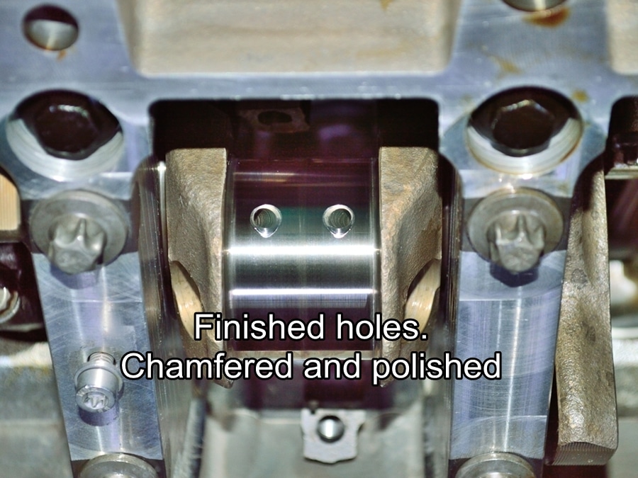
#56
I chamfered each set of rod journal holes as I moved down the crankshaft replacing the bearings. If you do this make sure that you chamfer the “trailing” edges of the holes.
This picture shows a chamfered and cleaned journal.
#57
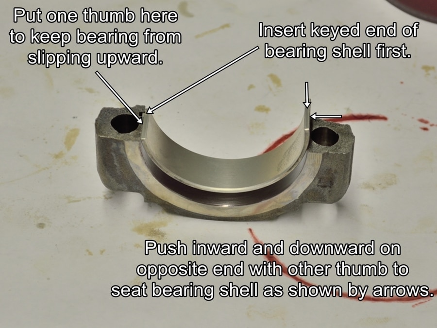
At this point the rod caps, connecting rod big ends and rod journal for the pair of bearings you are working on should be clean and dry.
Install a lower (702 Red) bearing shell into each of the rod caps as shown in the picture. Engage the keyed end of the shell into its slot first, then while pushing inward and downward on the opposite end of the bearing shell, fully seat the bearing shell into the cap.
By pushing inward you help prevent the sharp edge of the cap from shaving a little material off of the back side of the bearing shell when pushing it downward into place. I hope that makes sense.
Repeat the same procedure on the connecting rod big ends with a set of upper bearing shells (703 Blue). This is a little more difficult because of the limited space to work in. Take care when working on the rods to not let them contact and scratch the crank journal.
#58
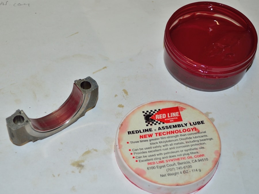
Apply a film of the assembly lube of your choice to both upper and lower bearing surfaces. Using your fingers to pull down on the connecting rods, and your thumbs to guide them, pull the rod big ends down to seat them onto the crankshaft journal.
Install the two rod caps onto THEIR mating connecting rods with new bolts and lightly snug the cap bolts.
If using OEM BMW bolts, lube under the bolt heads and the bolt threads with motor oil. If using ARP bolts, grease the bolts according to ARP’s directions.
Rotate the crankshaft clockwise until the next pair of rods are at the bottom of their stoke. Repeat the previous steps until you have worked your way through all ten bearings. Again, I prefer to wait to torque all of the rod bolts until after replacing all of the bearings.
#59
Once all rod bearings have been installed you can go ahead and torque the new rod bolts.
If you are using ARP bolts please refer to ARP’s torquing instructions.
If you are using OEM BMW bolts you will need to use the procedure outlined in the next instruction.
The OEM BMW rod bolt torque procedure is a real PITA. You will need a good digital torque wrench with a “torque angle” feature. I don’t recommend performing this procedure without a torque angle gauge.
You will need to start at one end and work your way up the crankshaft one rod at a time. Each rod bolt will need to be torqued three separate times in three steps to temper the bolts properly. Doing one connecting rod at a time, you need to torque each pair of bolts to 6Nm/4.4ft-lbs, then each pair of bolts to 20Nm/15ft-lbs, then turn each pair an addition 130 degrees. You then need to loosen both bolts back to zero tension and then perform the entire torquing procedure two more times.
You will feel like your arm is going to fall off by the time you are finished. Just go slowly and be careful to not miss a torque sequence. The are some bolts where you won’t have room for a full 130 degree swing. Sometimes you will need to break the angle into two or three steps.
Now that the connecting rods have been torqued, the next step will be to reinstall the oil pumps and set the VANOS pump gear backlash.
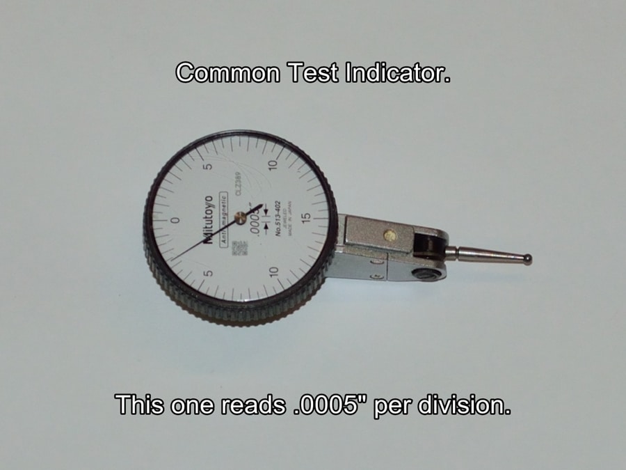
Before we get to that, I think a little information on the tools used would be helpful. If you are already familiar with the proper use of test indicators I’m sorry to bore you here. I’m including this information because there have been a lot of forum questions posted about the procedure and I have seen pictures posted by experienced mechanics showing the indicator incorrectly positioned for accurate measurement.
You will need to purchase, rent or borrow a test indicator and base to set the VANOS gear backlash. Since you will need to measure a backlash value between .0024″-.0031″, the higher the resolution of the indicator the better. You will find them available in .001″, .0005″ & .0001″ per division resolutions. The .0001″ resolution indicators are quite expensive and are unnecessary for this procedure. I highly recommend a .0005″ per division indicator if you can swing the extra cost.The next four steps give you some basic information on test indicators and their bases.
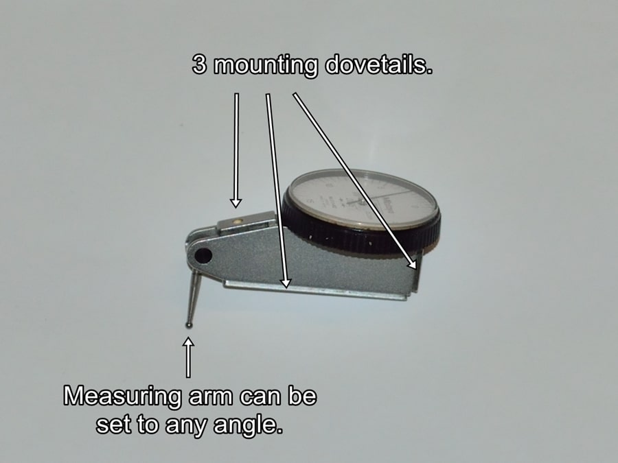
This is a typical test indicator used for setting VANOS gear backlash. There is nothing special about the factory BMW tool, it is just a standard test indicator with a mini magnetic base.
These can run you anywhere from $20.00 for a low quality Chinese indicator, up to $200.00-$300.00 for a top quality Japanese or U.S. indicator. This is a Japanese Mitutoyo indicator with a resolution of .0005″ per division. Most low price indicators have a resolution of .001″ per division. Since you need to measure a lash of .0024″-.0031″ the higher resolution one is preferred.
As shown in the picture, most indicators will have three dovetail mounts which will allow you to mount them in three different positions depending on clearance issues and preference.
The measuring arm can be moved to any position you need with respect to the indicator. The angle of the arm to the indicator will not affect the measurement, but the angle of the arm to the item being measured is critical.
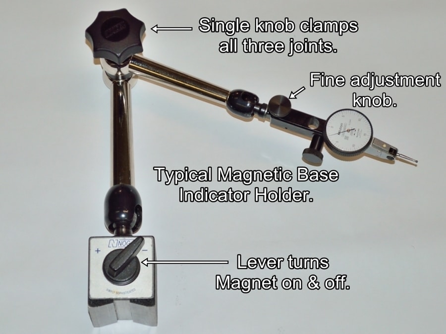
This is a standard magnetic base indicator holder. This is the style that comes with the BMW factory tool. This type is typically magnetically stuck to a piece of steel that is bolted to the engine somewhere. One of the oil pan threaded holes works well for this.
The big knob at the junction of the two arms loosens and tightens all three movable joints at the same time to lock the indicator arms into the position that they have been set.
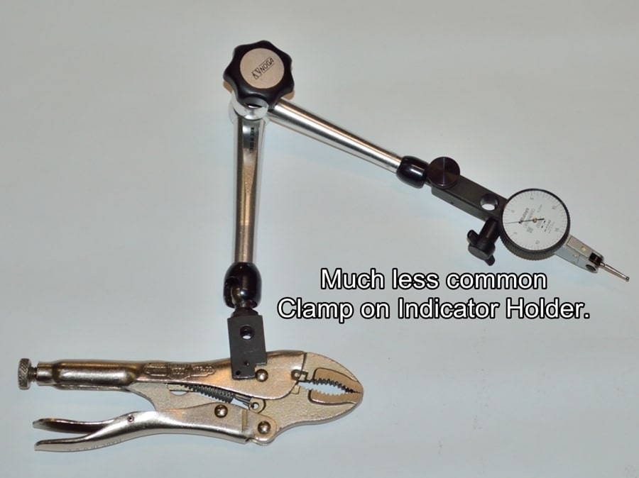
This is a very handy clamp on indicator holder. As you can see it is just a standard adjustable arm mounted to a pair of vise grip pliers instead of a magnetic base.
I don’t even remember where I got this one but it is very handy for working on engines.
Now that you are educated on test indicators you can go ahead and reinstall the main oil pump and the VANOS high pressure pump, working backward from steps #36 to #31.
Make sure to lube the chain tensioner piston parts and install them into their bore before installing the main oil pump gear. I used medium strength threadlock on the pump gear nut.
You can torque the main oil pump bolts but leave the VANOS pump bolts just snug.You are going to want the bolts tight enough to allow the VANOS pump to be able to be moved when tapped with a rubber or plastic mallet, but not able to be moved by hand.
Start by setting the VANOS pump to a position where you can feel a very small amount of free play when trying to rotate the sprocket back and forth, then snug the bolts as stated in the previous paragraph.
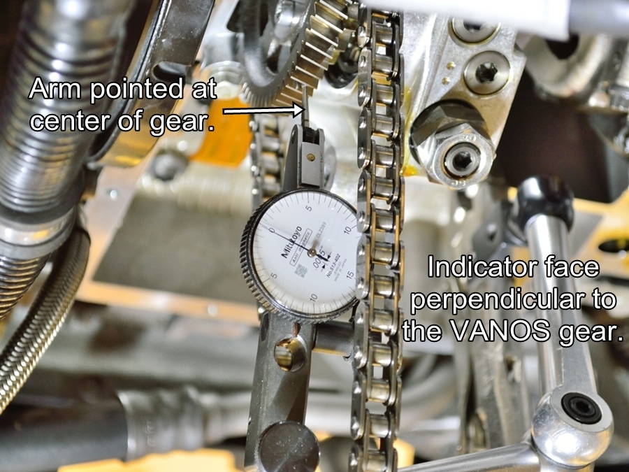
Install your test indicator so that its mount is rigid and the indicator can easily reach the gear, then position it as follows:
Proper position of the indicator and the indicators measuring arm is critical for obtaining accurate measurements.
As shown in the next picture, the face of the indicator needs to be perpendicular to the sides of the gear, not perpendicular to the gear tooth. If you measure with the indicator positioned perpendicular to the gear tooth you will end up with a measurement that is the lash value times the cosine of the gear tooth helical angle. This value will be less than the actual value you are looking for.
The indicators measuring arm needs to point at the center of the gear. In other words, if you visualize a line through the center of the measuring arm, and extended outward, it would intersect the center point of the gear. The arm can be at any angle with respect to the indicator body, but must be pointed at the center of the gear.
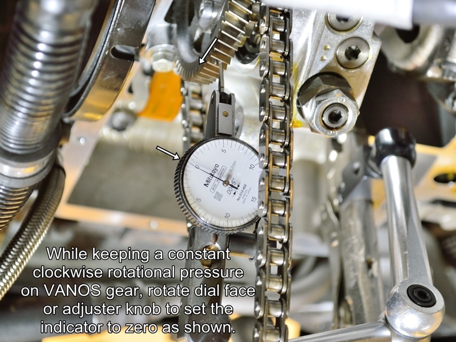
#60
This picture shows the indicator properly positioned to accurately measure the gear backlash.
This picture also shown only the VANOS pump reinstalled. It does not matter whether you set backlash with both pumps installed or just the VANOS pump.
#61
Now that the indicator is set-up properly we can begin the backlash measurement.
While applying a constant clockwise (as viewed from the front of the engine) rotational pressure to the VANOS gear with one hand, rotate the dial face or the fine adjustment knob (if your mounting base has one) to set the indicator needle to the zero position as shown.
A note about my interpretation of the proper backlash setting:
BMW TIS states to position the VANOS pump to obtain a backlash setting between .06mm & .08mm (.0026″-.0031″). This is not difficult to do, the problem is once the backlash is set, as you torque the bolts to spec you are moving the pump gear ever so slightly closer to the crankshaft gear, which causes the backlash reading to decrease. Since BMW make no mention in TIS of rechecking the backlash after torquing the bolts, does the decrease in backlash matter? I would bet that you couldn’t find anyone at BMW to answer that question.
My solution (so I can sleep at night) is to set the backlash at the high end of the specification with the bolts snug, then make sure that it does not fall below the low end of the spec once the bolts are tight. If it does, you may need to start with the bolts a little tighter during the adjustment procedure.
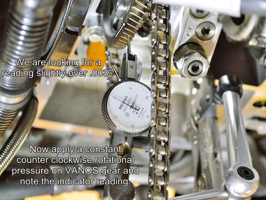
#62
Now apply rotational pressure in the opposite direction and note the indicator reading.
We are shooting for .0031 inches with the bolts snug which we hope will be no less than .0026″ with the bolts torqued to spec.
Use a plastic or rubber hammer to tap the VANOS pump left or right as needed to obtain a measured backlash of slightly over .0031″. This will probably take several attempts at tapping the pump back and forth to get it right.
Once you are satisfied that you have the backlash properly set, torque the bolts to 10 Nm (7.4 ft/lbs). After torquing, recheck the backlash reading and verify that it is not below .06mm (.0026″). If the reading is below minimum spec, it’s up to you whether you want to keep working at it or not. Since BMW TIS does not state to recheck the backlash after torquing the bolts, a backlash setting below .0026″ may be fine.
You are now ready to start reassembling everything in reverse order. I hope you took a lot of pictures and have a good memory. Good luck and enjoy that V10!