Pri Chain Tensioner Spring – OEM Part # 11411706809
Pri Chain Tensioner Piston – OEM Part # 11311703747
Intake Cam Sprocket – OEM Part # 11361744263
Exhaust Cam Sprocket – OEM Part # 11361744262
Main Drive Sprocket – OEM Part # 11361438565
****** IMPORTANT - IMPORTANT - IMPORTANT - IMPORTANT - IMPORTANT ******
Read the four paragraphs below before you begin any disassembly of your vehicle.
I HIGHLY recommend that you completely read through the entire instructions several times before you begin to familiarize yourself with the procedure. Pay close attention to the first two steps, they will need to be performed during the initial disassembly phase of the engine!
If you cannot have a computer nearby during this procedure, print off these PDF instructions. I highly recommend using a laptop computer at the vehicle location if available over using the printed PDF instructions. The ability to enlarge the pictures on a computer display will ensure that all the important detail information in the pictures will be visible.
DO NOT attempt to perform these instructions using a “Smart Phone”! The pictures contain important details that would be very difficult to view properly on the small display of a smart phone.
Make sure that you read each step fully from beginning to end before you perform any part of a step. Some steps contain multiple procedures, and some steps contain information at the end of the step, that is crucial to completing the step properly. The only time anyone ever encounters a problem when using these instructions is when they start a step before they have read the entire step through first.
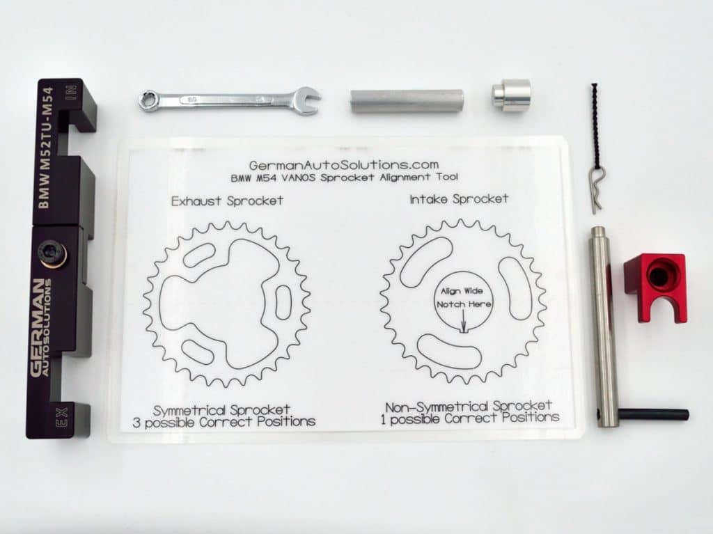
What’s in the German Auto Solutions BMW M52tu-M54 Personal Cam Timing Tool kit.
#1
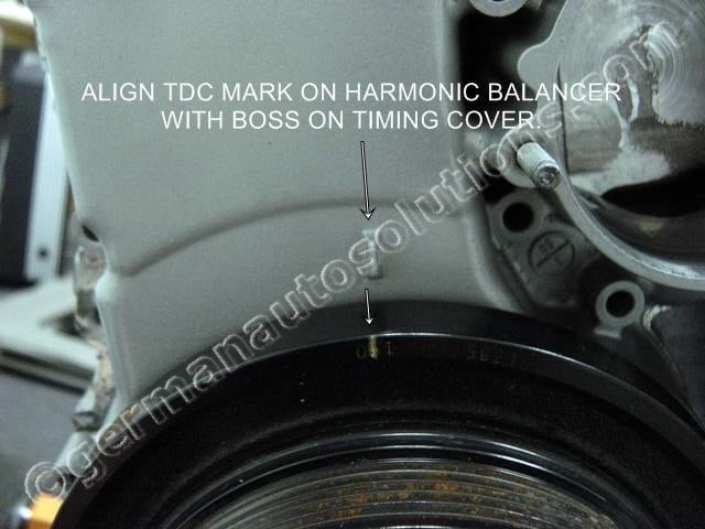
Start by setting the crankshaft to TDC. There is an alignment mark on the harmonic balancer that needs to align with the boss on the front timing cover as shown in the picture. It’s a good idea to highlight the mark to make it more visible. In the picture at left I used a pick tool and some yellow paint to highlight the mark.
There are two possible positions for the crank at TDC that are 360 degrees apart. The next instruction block will show how to determine if you have the correct position.
#2
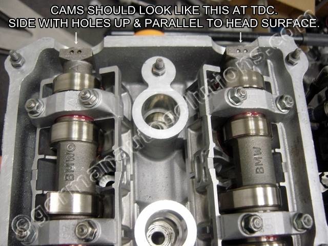
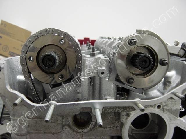
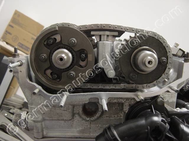
After setting the crankshaft to TDC, check the position of the cams. Note the two holes facing up on the rear ends of the camshafts in the picture at left. If you do not see the two holes facing up you will need to rotate the crankshaft one full revolution and align the TDC marks again.
Do not proceed until you verify that the holes on the cams are facing up and the the crankshaft is at TDC.
#3
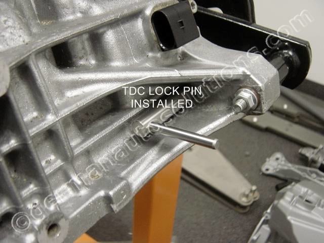
Locate the TDC lock pin that came in the tool kit. The lock pin is inserted though the engine block on lower rear drivers side on the engine.
There is a plastic plug installed into this hole by BMW to help keep dirt out of the hole. You will need to remove this plug to use the lock pin. The hole will still have some dirt and oxidation build up on the I.D. that will need to be cleaned out before installing the pin. A wire “bottle style” brush that fits into the hole works best. Clean the hole until the lock pin will slide through.
#4
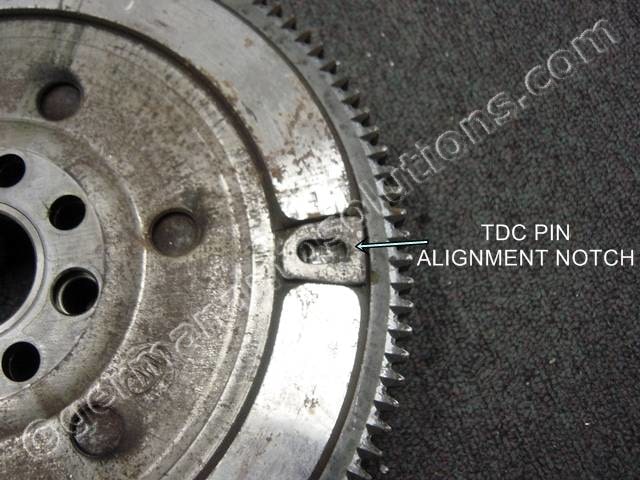
This is a view of the lock pin hole in the flywheel or automatic transmission flex plate. This is what the end of the pin needs to slide into.
Verify the pin is fully engaged into the hole by trying to rotate the crankshaft with the pin installed. If you can still rotate the crank, rock the crankshaft back and forth slowly near TDC while pushing on the pin until it drops into place and locks the crank. This will be a two person job.
#5
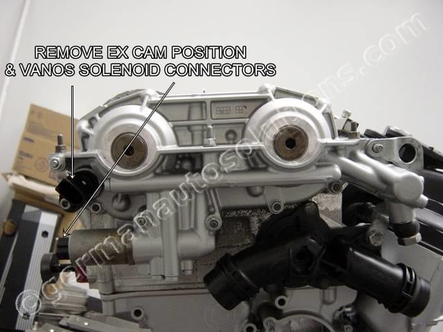
Unplug the electrical connectors for the exhaust cam position sensor and exhaust VANOS solenoid.
#6
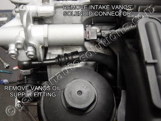
Unplug the electrical connector for the intake VANOS solenoid.
Disconnect the oil feed fitting to the VANOS unit.
#7
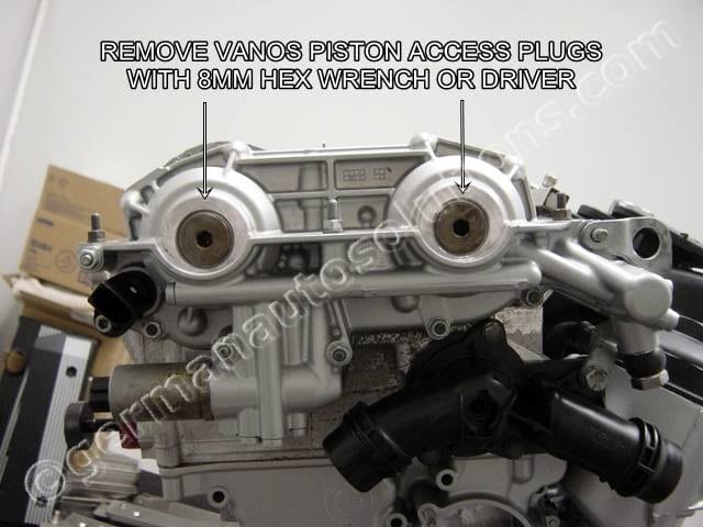
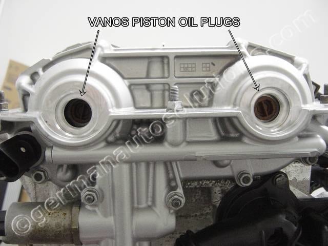
Remove the 2 VANOS piston access plugs using an 8mm Allen wrench or driver.
#8
There are two plastic oil plugs behind the access covers. These will be removed in the next step.
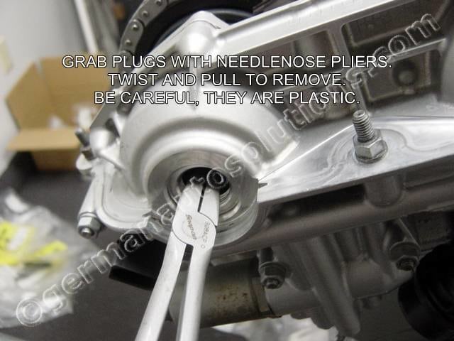
#9
Grab the divider in the middle of the plug with some needle nose pliers, twist and pull until the plugs pop out.
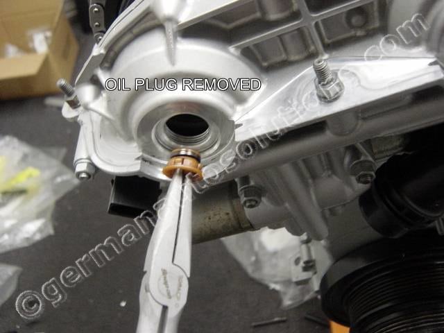
#10
This is what the plug looks like. You will want to replace the o-ring or the entire plug during reassembly.
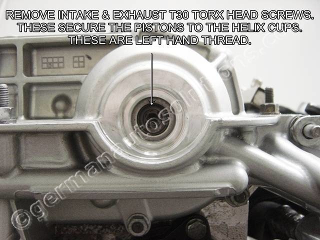
#11
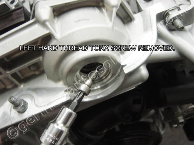
Using a T30 Torx driver, remove the intake and exhaust piston screws.
NOTE: THESE ARE LEFT HAND THREAD.
#12
Left handed piston screw removed.
#13
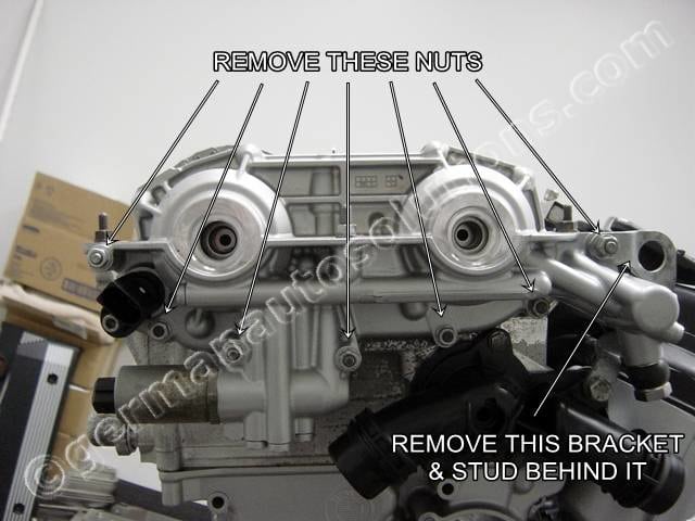
Next we will be removing the VANOS unit from the cylinder head. Remove the hardware securing the VANOS unit shown in the picture.
10, 11 and 13mm sockets will be required here.
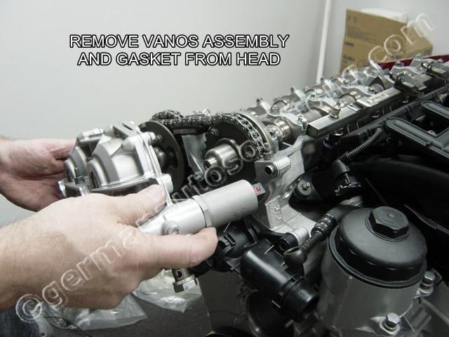
#14
Remove the VANOS unit from the cylinder head. You may need to tap it with a rubber mallet to break the gasket loose.
Once removed, thoroughly clean the gasket surfaces of both the cylinder head and the VANOS unit. Remove all traces of old gasket material and RTV sealant.
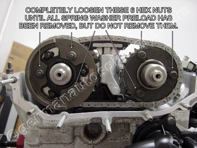
#15
Using a 10mm socket, completely loosen the six nuts shown in the picture.
Do not remove them yet
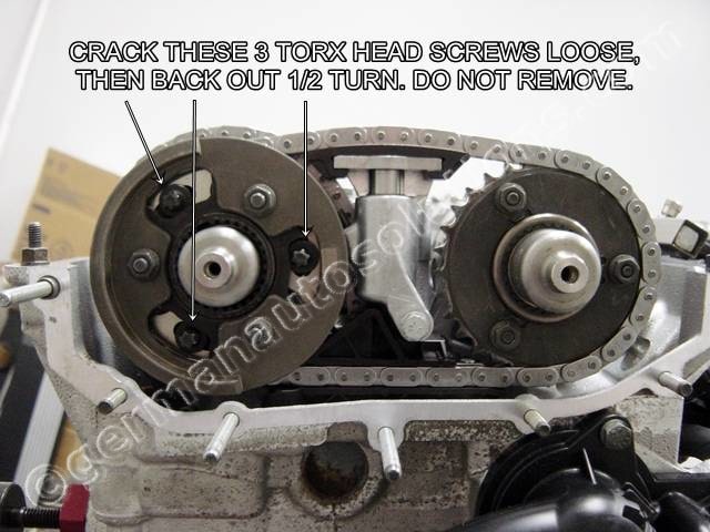
#16
Using an E8 Torx socket, crack loose the three Torx head bolts shown in the picture.
Do not remove them yet.
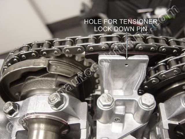
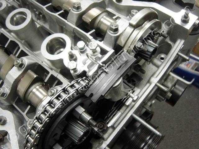
#17
Note the hole in the secondary timing chain tensioner shown in the picture.
This is where you will be installing the tensioner lock pin in the next step.
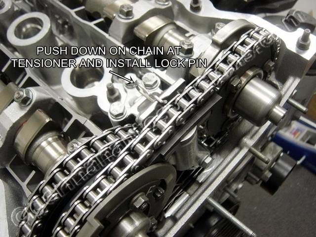
#18
Locate the tensioner lock pin that came in the cam tool kit. Press down on the secondary timing chain at the tensioner guide shoe, then insert the lock pin as shown.
You need to press the guide shoe down as far as it will go. The pin only needs to protrude far enough to overlap the shoe. The pin does not need to extend under the chain. It’s a good idea to tie piece of string or wire to the loop in the lock pin to prevent the possibility of dropping it into the engine.
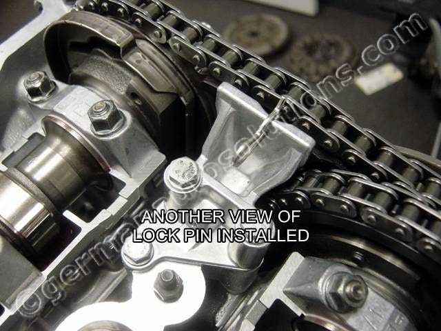
#19
View of lock pin properly installed.
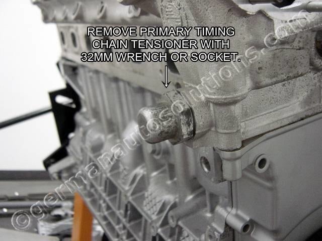
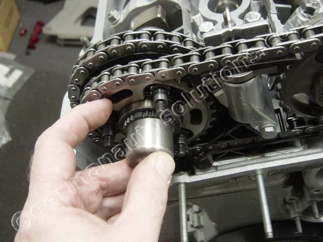
#20
Remove the primary timing chain tensioner with a 32mm (1-1/4″) socket or wrench.
#21
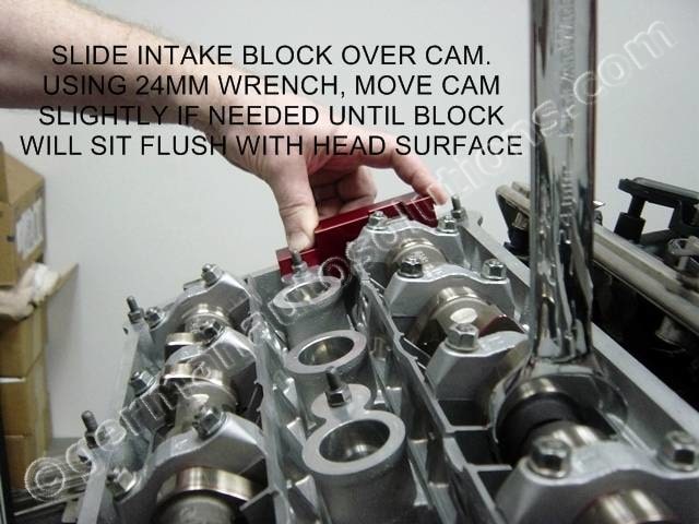
Locate the cam lock blocks from the tool kit. Starting with the intake cam, slide the block marked “IN” over the square end of the intake cam as shown in the picture.
Preview the pictures in steps 22-24 for a better view of the way the blocks need to be installed.
Using a 24mm wrench at the spot shown, if necessary, slightly rock the cam forward and backward while pushing down firmly on the lock block to seat the block flush with the head surface. The block should slid on easily and be obvious when seated properly.
#22
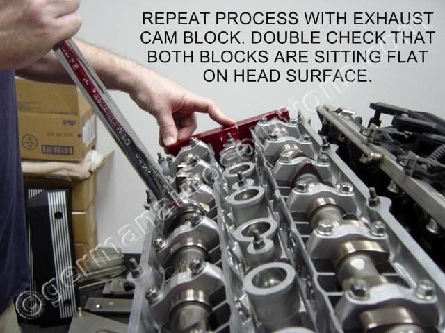
Repeat the process with the “EX” lock block on the exhaust camshaft.
Again, go slowly, be careful, and do not force the block into place.
#23
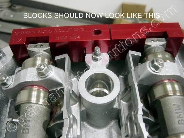
This is what the installed lock blocks should look like. Verify again that they are both fully seated flush with the cylinder head surface.
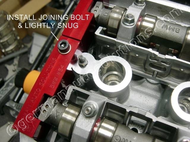
#24
Locate the supplied 8mm socket head cap screw.
Using a 6mm Allen wrench or driver, lightly snug the screw to lock the two blocks together
#25
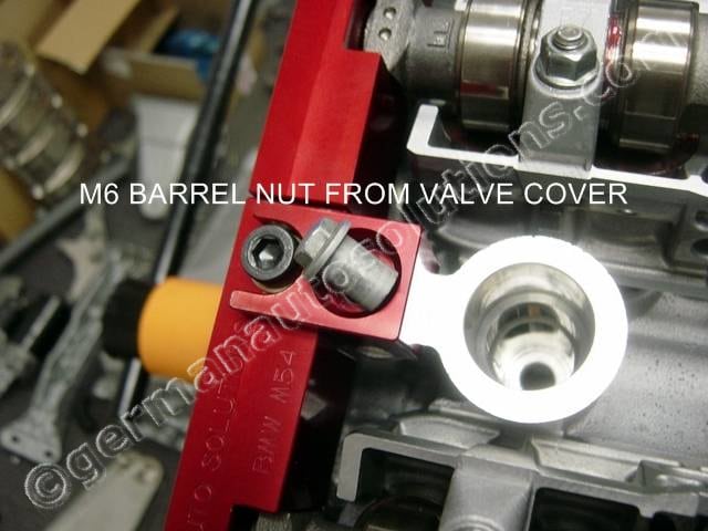
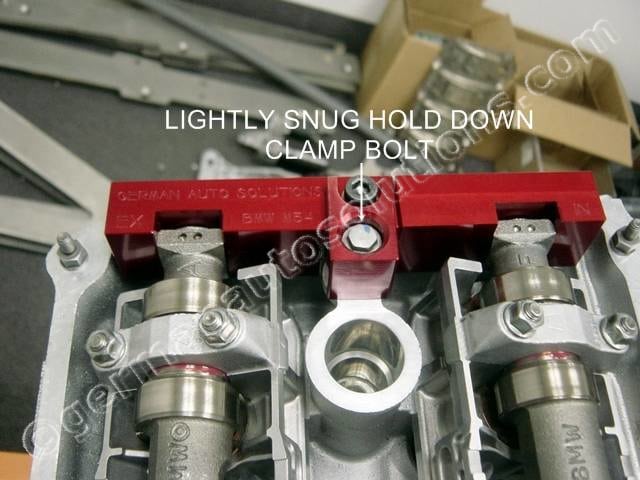
Locate the lock block clamp from the tool kit.
Position the clamp over the valve cover stud as shown. Locate one of the OEM valve cover barrel nuts from the valve cover dis-assembly.
#26
Lightly snug down the barrel nut to hold the lock blocks in place.
#27
Remove the three already loosened 6mm hex nuts holding the intake sprocket spring washer in place.
#28
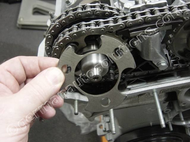
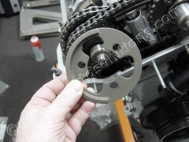
Remove the intake sprocket spring washer.
#29
Remove the three already loosened hex nuts holding the exhaust cam position sensor plate.
#30
Remove the exhaust cam position sensor plate.
#31
Remove the exhaust sprocket spring washer.
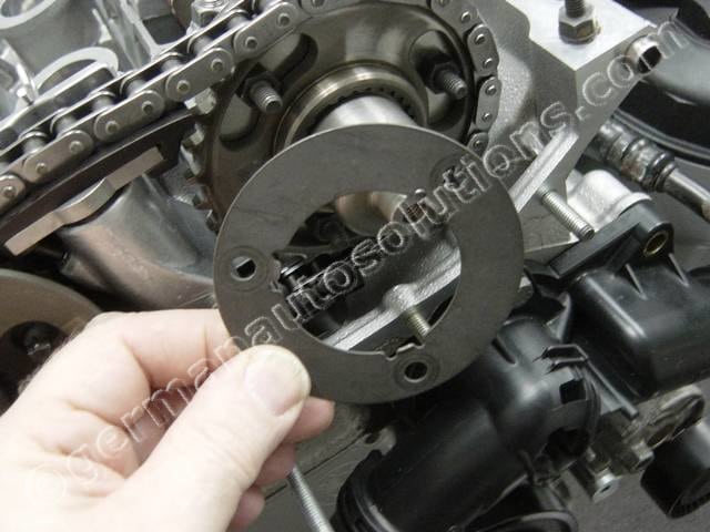
#32
The exhaust sprocket thrust washer is a tight fit over the shoulder studs, you need to pull it off straight or rock it to keep it from binding on the studs.
#33
Remove the exhaust sprocket thrust washer.
It’s definitely not critical, but you may want to mark the side that faces outward for proper reassembly.
The part is symmetrical and will work properly with either side facing out. Marking it just keeps previous wear surfaces mated to their original parts.
#34
Remove the three already loosened E8 Torx head bolts holding the exhaust cam sprocket in place, but do not remove the sprocket yet.
#35
While holding the intake cam sprocket from sliding off the cam, remove the intake cam helix cup by pulling outward on it.
The intake and exhaust helix cups are identical, but should be reinstalled back on the cam that they were removed from. An easy way to keep them separate is to put all the intake cam parts in one plastic bag, and all the exhaust in another.
#36
Intake cam helix cup removed.
#37
Support the exhaust cam sprocket as you remove the exhaust cam helix cup in the same way as you did the intake.
Once the cup is removed the exhaust sprocket will try to fall forward. You want to remove the both sprockets and secondary timing chain together as an assembly, so preview the next step to see how the chain/sprocket assembly will be removed. Remove the cup, then the chain/sprocket assembly.
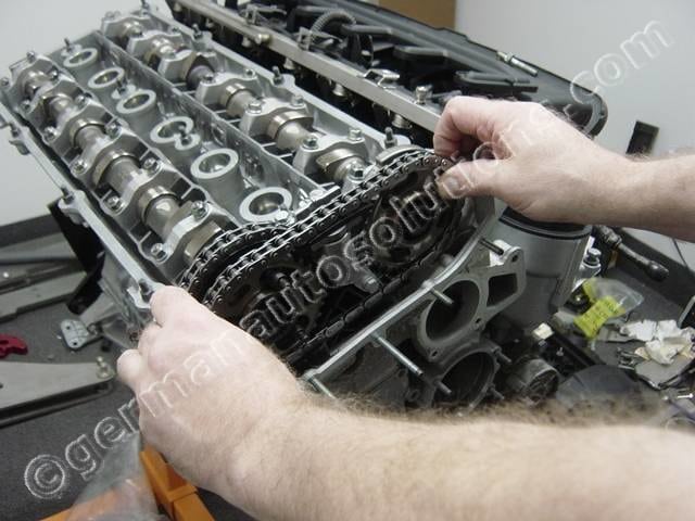
#38
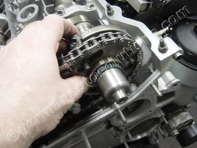
You remove the secondary timing chain and sprockets by grasping the outside edge of both sprockets, then pulling straight back.
#39
Sprockets being removed.
#40
Depending on how you grasped the exhaust sprocket in the previous step, you may have already removed this part. If not, remove the exhaust sprocket helix flange.
#41
If you are not going to replace the secondary timing chain tensioner, intermediate timing chain guide, camshafts or remove the cylinder head, you are finished with the dis-assembly. If you are going to replace any of these, continue until you have reached the end of the dissassembly instructions.
Using a 10mm socket, remove the three top and one side bolt securing the secondary timing chain tensioner.
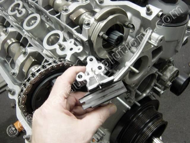
#42
Remove the secondary timing chain tensioner.
#43
Using an E8 Torx socket, remove the two Torx head screws securing the intermediate timing chain guide, them remove the guide.
#44
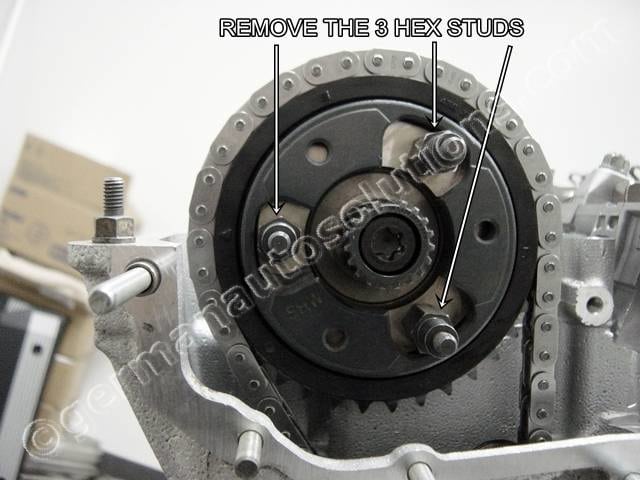
If you are not going to remove the camshafts then you are finished with the disassembly.
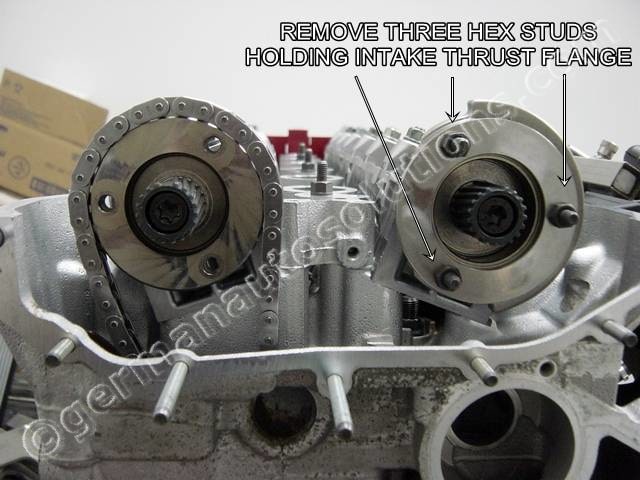
If you are going to remove the camshafts, then proceed by removing the three hex studs on the exhaust cam flange with an 12mm deep well socket.
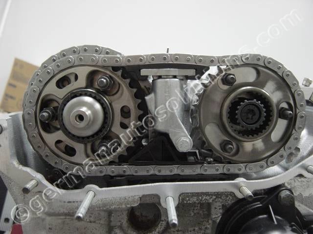
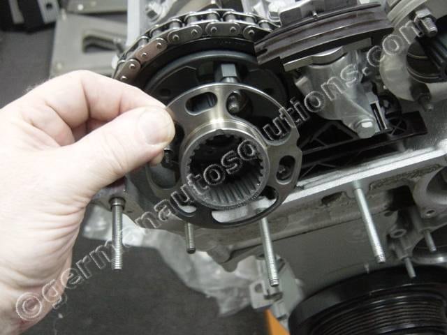
#45
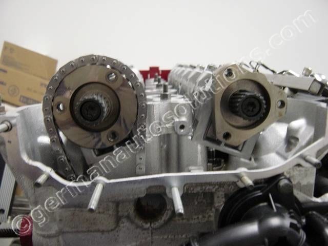
With the hex studs removed, slide the main drive sprocket toward you then down.
This will give you enough slack to slip the timing chain off of the sprocket.
#46
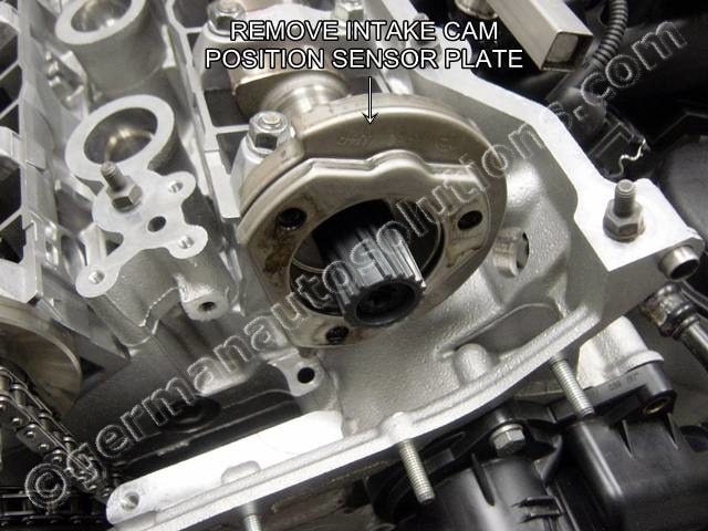
Using a 10mm deep well socket or wrench, remove the three intake cam hex studs shown.
#47
Remove the intake cam position sensor plate.
#48
You have now completed the total disassembly of the VANOS system.
You have completed the disassembly portion of these instructions.
The next sections covers reassembly and timing of the VANOS system.
Depending on the engine service that you have been performing, your VANOS system may not have been completely disassembled.
If your VANOS has not been completely disassembled you will need to skip ahead in the instructions until you find the point which matches the current state of your engine.
Before you begin reassembly, make sure that you have:
The crackshaft postioned at #1 cylinder TDC.
You have the TDC lock pin installed.
You have the camshafts positioned with the hoses facing upward.
You have the cam lock blocks installed.
You have the timing chain tensioner removed.
#1
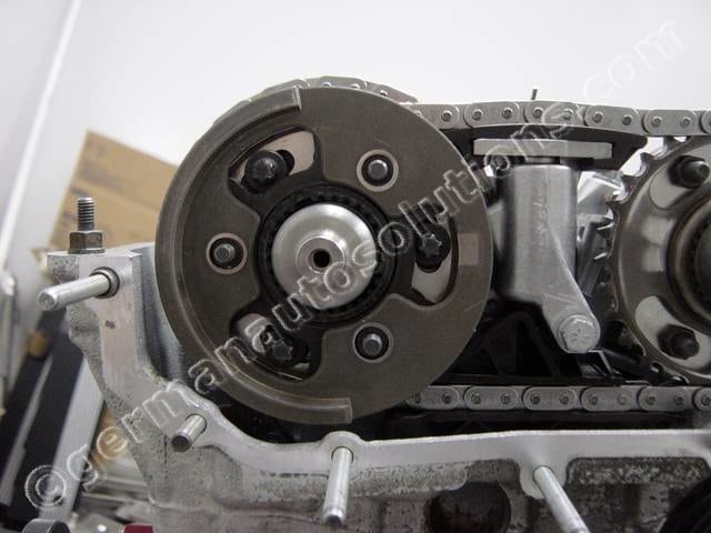
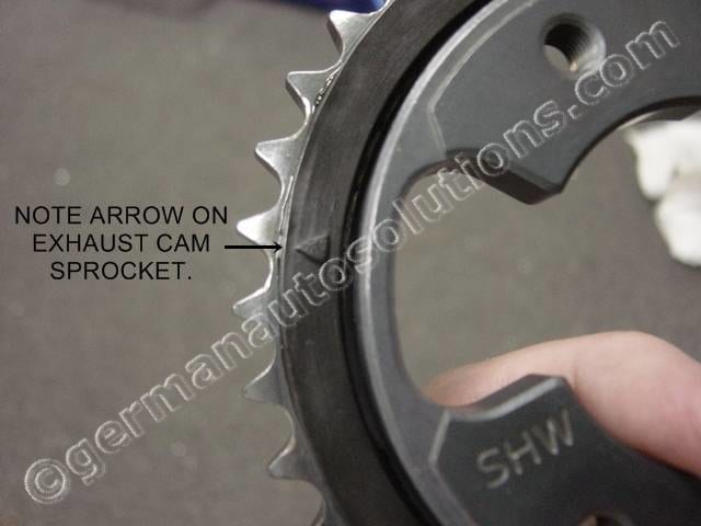
Start by locating the main exhaust cam sprocket.
Find the timing arrow on the sprocket, it will be aligned to the head surface in the next step.
#2
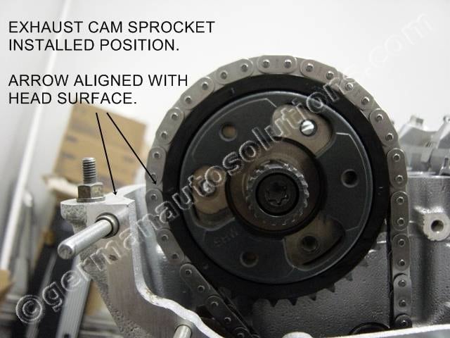
You need to slip the sprocket up under the timing chain and over the exhaust cam flange. Once slipped into place, rotate the sprocket counter clockwise to take up any chain slack.
Compare the timing arrow location to the top surface of the cylinder head. They should line up as shown in the picture to the left.
You will probably have to slide the sprocket off the cam flange several times while rotating it a link at a time until it lines up properly with the head surface.
#3
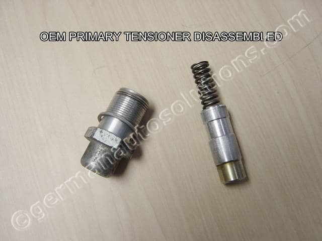
Locate the OEM tensioner.
We will be modifying it to work as a rigid tensioning tool.
Slide the plunger out and remove the spring.
#4
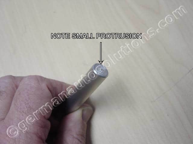
Locate the longer of the two aluminum pins which came in the kit.
Find the end with the small protrusion, this end goes in first in the next step.
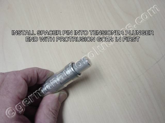
#5
Slide the aluminum spacer pin into the tensioner plunger protrusion end first.
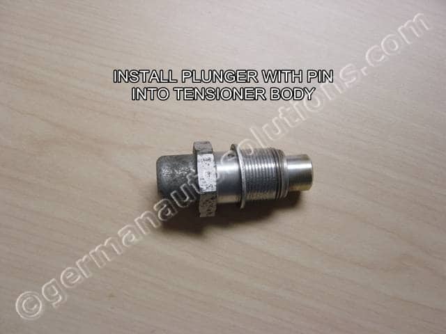
#6
Slide the plunger with pin into the tensioner body.
You now have an inexpensive tensioner tool.
#7
Install the modified tensioner into the OEM tensioner location.
Slowly finger tighten the tensioner body just until you feel a little tension. All you need to do here is take up the timing chain slack enough to verify that the exhaust sprocket is properly indexed to the chain.
If you need to tighten the tensioner all the way in to remove the slack in the chain, it is another indication that the chain is stretched and needs to be replaced.
#8
Verify that the exhaust cam sprocket is still properly aligned to the cylinder head top surface. If not, fully loosen the tensioner and go back to step #2.
Once you have verified proper alignment, install and torque the 3 hex studs shown to 20Nm-15ft/lb. Medium strength (blue) threadlock is optional but suggested.
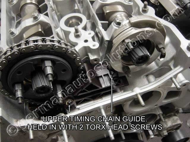
#9
You will now install the middle timing chain guide.
This guides both the primary and secondary timing chains. Unless you have a very low mileage car, I suggest you replace it with a new OEM guide. The guide is held in place with 2 torx head bolts.
Torque to 10Nm-7.5ft/lb
#10
Locate the secondary timing chain tensioner.
If the lock pin is not still in place from the disassembly procedure, compress the tensioner and install the tensioner lock pin. The secondary chain tensioner is another recommended replacement item.
#11
Install the tensioner, snug the 4 mounting bolts, then torque to 10Nm-7.5ft/lb.
#12
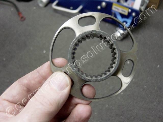
Locate the exhaust cam helix flange.
Note the orientation shown. The wide gap in the inside tooth area goes up.
#13
Apply some motor oil or assembly lube to the front and back surfaces and helix splines of the flange.
Apply some motor oil or assembly lube to the exhaust cam helix splines.
Slide the exhaust cam helix flange over the hex studs with the wide gap in the helix facing up.
#14
This is what it should look like.
I’m holding it up with my finger because it wants to fall off if you don’t. You will be installing the exhaust helix cup in the next step which will allow the helix flange to stay in place on its own. You might want to have it handy before you complete this step.
#15
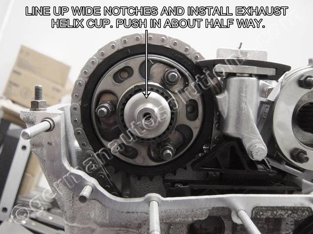
Locate the exhaust helix cup.
Intake and exhaust cups are identical, but if you are reinstalling used cups, it’s best to keep the cups matched to the cams they came off from.
Apply motor oil or assembly lube to the helix cup inside and outside splines. Line up the wide teeth on the exhaust cam helix cup with the wide gaps on the camshaft and helix flange. Install the helix cup and push in about half way. You might have to fiddle with it a little bit to get it started.
#16
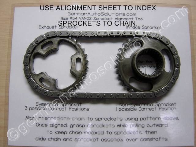
This is an easy but critical step.
Lay the intake VANOS sprocket, exhaust VANOS sprocket, and secondary timing chain on the alignment sheet as shown on the left. Align the wide notch on the intake sprocket helix as shown on the sheet.
While keeping the intake sprocket aligned to the sheet, keep repositioning the exhaust sprocket until they both line up with the outline. The exhaust sprocket technically does not have a front or rear so just pick a side to face up. As shown on the alignment sheet, the exhaust sprocket is symmetrical and has 3 possible correct orientations. This is hard to get wrong. If you have a one tooth misalignment it will be obvious.
#17
Apply a film of oil or assembly lube to the front and back faces of both sprockets, the helix splines on the intake sprocket, and the helix splines on the intake cam before installation.
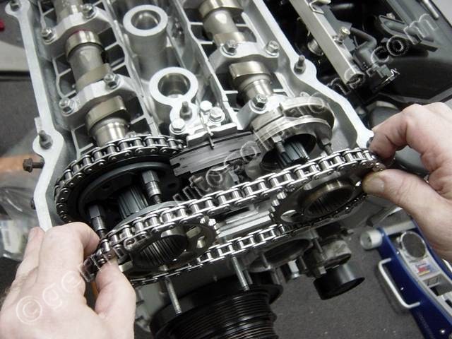
Preview steps 18, 19 and 20 before installing the chain and sprocket assembly. This will help you understand how the assembly will be positioned.
Grasp the chain and sprocket assembly as shown. As you lift the assembly off of the alignment sheet, keep the protruding section of the intake cam sprocket facing toward the engine. Slide the assembly onto the cams while keeping the wide notch on the intake sprocket splines facing up.
#18
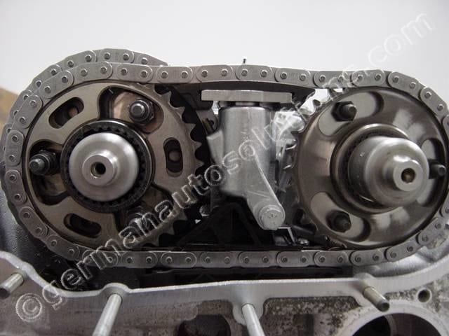
Slide the chain and sprocket assembly over the cams as shown.
Please ignore the fact that the exhaust helix cup is not shown installed in this picture. Your exhaust helix cup should be installed.
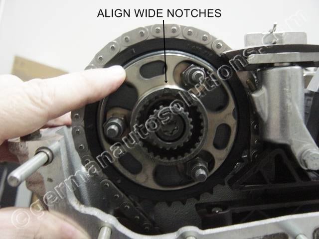
#19
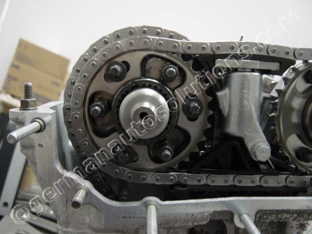
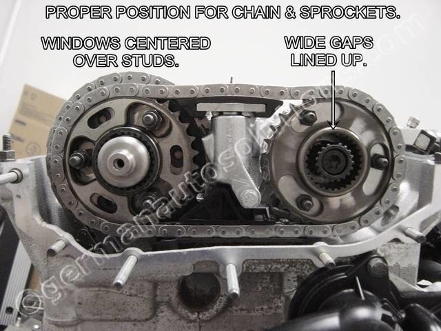
This is how it should look.
Make sure everything lines up as shown in the picture.
With the wide gaps on the intake splines lined up, the oval openings in the exhaust spocket should be centered over the exhaust hex studs. If you installation does not look exactly like this, stop and find out why.
#20
Locate the intake helix cup and apply some motor oil or assembly lube to the outside and inside helix splines.
Now install the intake helix cup using the same procedure you used for the exhaust side. Push the intake cup in just until the splined section is flush with the sprocket as shown in the picture.
#21
Install the 3 torx head bolts as shown.
Tighten them finger tight, then loosen 1/4 turn.
#22
Locate the intake cam spring washer and apply some oil or assembly lube to the back side.
Install over the threaded studs.
Note – the bent tabs face outward. Sometimes these will have a “FRONT” marking on the outside face.
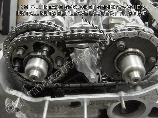
#23
Install the three 6mm hex nuts and finger tighten just until they contact the spring washer.
#24
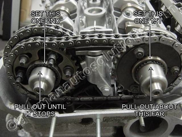
Starting with the intake helix cup, position the cups as shown in the picture. You want a little bit of the intake cup splines to be protruding as shown. After setting the intake cup, pull the exhaust helix cup ouward until it stops.
Tighten the 3 intake sprocket hex nuts until snug, then back the off 1/2 turn.
Tighten the 2 upper exhaust sprocket Torx bolts until snug, then back off just enough to break them loose. Next, snug the bottom Torx bolt, but DO NOT exceed 5 ft/lbs. Be careful that you do not disturb the helix cup position while working with the Torx bolts. You might want to pull out on the cup while tightening the bottom bolt.
#25
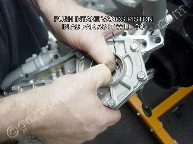
Locate the VANOS unit, we will be setting it up to be used as an alignment plate.
From the camshaft side of the VANOS unit, as shown in the picture, push the intake piston in as far as it will go. Since there will probably by oil still trapped in the unit make sure that you have fully pressed the piston in until it has hit it’s hard stopping point.
#26
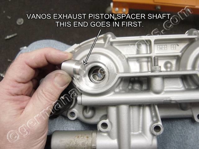
Locate the other aluminum spacer that was included in the tool kit.
Drop the pin into exhaust piston access hole as shown. The smaller diameter end goes in first.
#27
German Auto Solutions exhaust piston spacer pin properly installed.
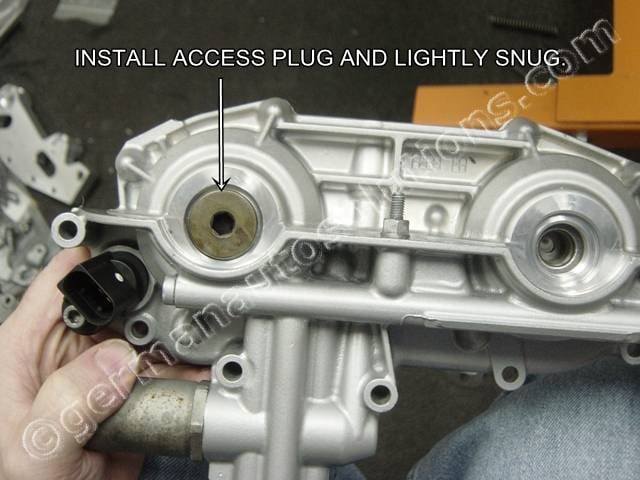
#28
Locate one of the threaded access covers and screw it in over the spacer pin. Just lightly snug into place.
#29
Make sure that cylinder head and VANOS gasket surfaces are perfectly clean with all traces of the old gasket removed.
Any pieces of old gasket material or dirt caught between the VANOS unit and head could have a minor effect on timing accuracy. Slide the modified VANOS unit onto the cylinder head studs.
Do not try to push it all the way on yet.
#30
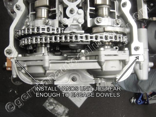
Push the VANOS unit on just far enough so that it contacts the protruding helix cups.
This will be approximately up to the two alignment dowels as shown in the picture.
#31
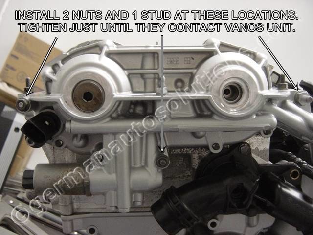
Install two of the OEM 6mm hex nuts and one OEM 8mm stud at the locations shown, but DO NOT tighten yet.
Screw them on just until they contact the VANOS unit.
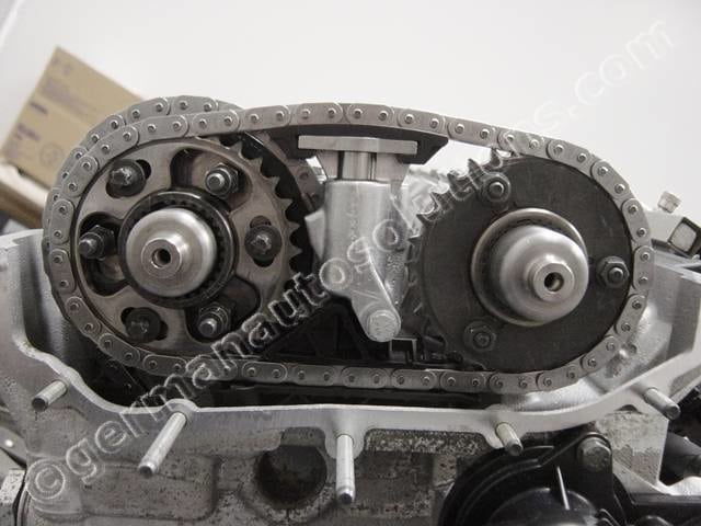
#32
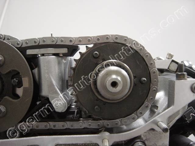
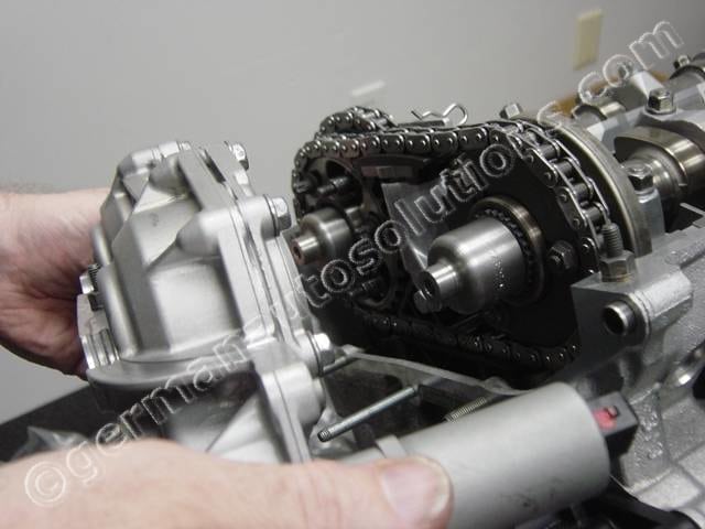
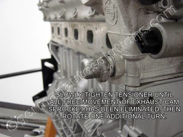
In this step we will pretension the primary timing chain. The tension is not overly critical. Once all the slack is taken out of the chain, further tightening does not accomplish anything. If you severely over tighten the tensioner you could damage the timing chain or guide.
The easiest way to set proper tension without over tightening, is to firmly grasp the exhaust sprocket, (the one furthest from the front of the engine, that the primary chain wraps around) and wiggle it back and forth as you tighten the tensioner. Tighten the tensioner slowly until you can no longer wiggle the exhaust sprocket, then tighten one more revolution.
Again, failure to be able to remove all the slack in the chain with the tensioner fully bottomed out against the head indicates a worn timing chain which should be replaced.
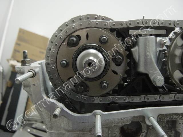
#33
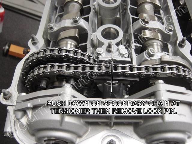
Push down on the secondary timing chain at the tensioner and remove the lock pin.
#34
You will now slowly tighten the left hex nut, and right hex stud, to draw the VANOS unit up to the head surface. This will push the helix cups into their proper timing position.
Turn them only 1/2 turn (180 degrees) at a time, alternating between the left nut and the right stud. You do not need to tighten the bottom hex nut yet. Watch the gap between the VANOS surface and head surface, you want to close that gap equally on the left and right sides as you draw the VANOS unit up to the head. Make adjustments to your tightening pattern if necessary to keep a uniform gap as you go.
Once the VANOS unit fully contacts the head surface you can tighten the bottom hex nut. Torque the two 6mm hex nuts to 10Nm-7.5ft/lbs and the 8mm stud to 24Nm-18ft/lbs.
#35
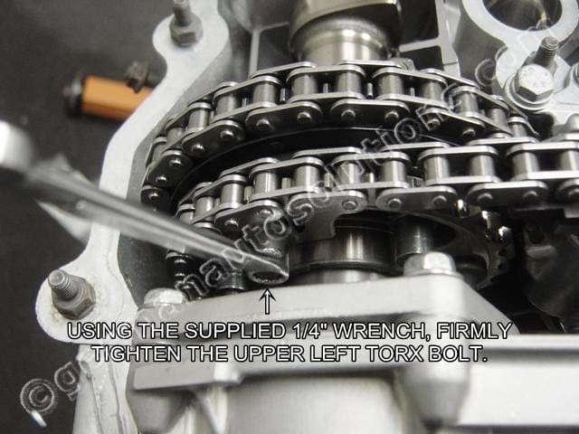
Using the 1/4 inch combination wrench supplied with the kit, firmly tighten the exhaust sprocket upper left torx bolt as shown.
#36
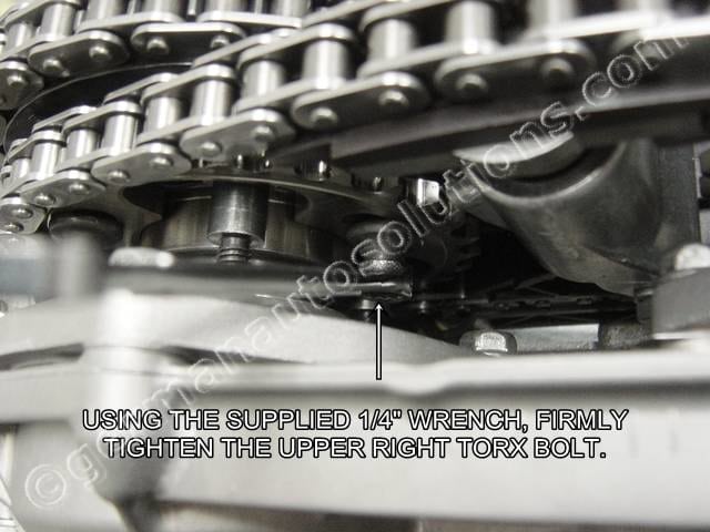
Using the 1/4 inch combination wrench supplied with the kit, firmly tighten the exhaustsprocket upper right torx bolt as shown.
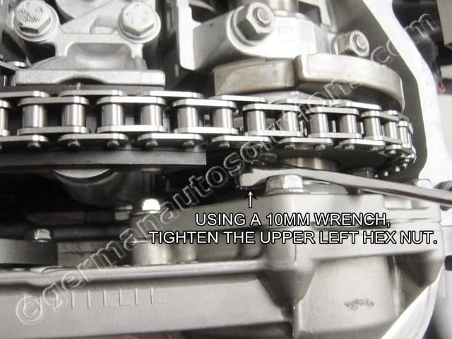
#37
Using a 10mm wrench, firmly tighten the intake sprocket upper left hex nut as shown.
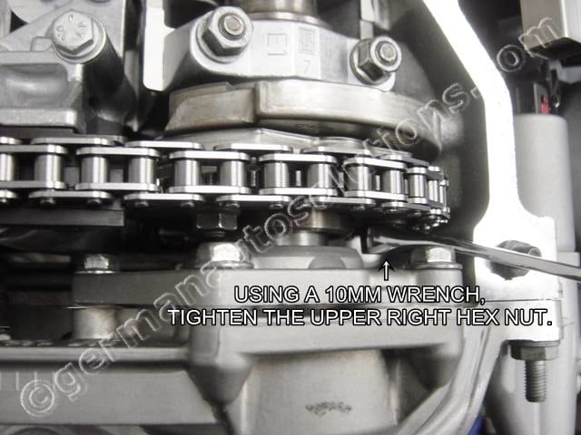
#38
Using a 10mm wrench, tighten the intakesprocket upper right hex nut as shown.
#39
Now remove the VANOS unit, then snug up the bottom hex nut and bottom torx bolt.
Do not torque yet.
Now remove the exhaust torx bolts one at a time while leaving the other two tight to prevent any possible change in the set alignment. Clean the one removed bolt, apply blue locktite, than torque to 20Nm-15ft/lbs.
Once you have one bolt torqued, remove the next and repeat the procedeure until all three torx bolts have been torqued.
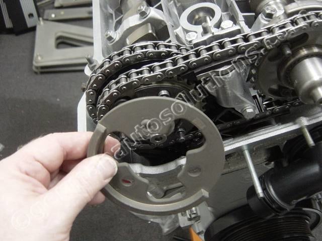
#40
Locate the exhaust sprocket thrust flange and apply a film of oil or assembly lube to both sides.
It doesn’t have a front or back and is another symmetrical part.
If you’re fussy you can usually tell which side was originally facing out by looking at the polished contact areas. The side with shinny spots on the very outside edge (like in picture) faces outward.
#41
Slide the exhaust thrust flange over the studs as shown.
Make sure you slide the flange past the threaded portion of the studs and onto the larger round section.
#42
Locate the exhaust sprocket spring washer.
Note the side marked “F” faces outward.
Slip the spring washer over the studs like the thrust washer.
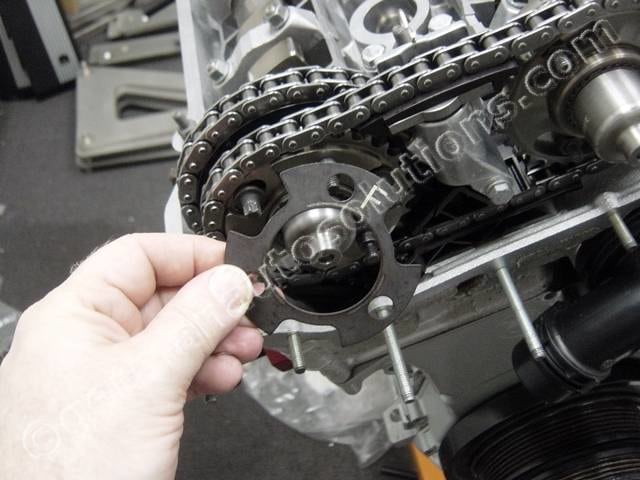
#43
Locate the exhaust cam sensor position plate.
Note the orientation, it has an arrow marking like the exhaust sprocket.
The arrow needs to line up with the left head surface.
#44
Install the cam sensor position plate as shown.
Install the three 6mm hex nuts and tighten a little at a time in a rotation pattern to compress the spring washer.
Do not torque them yet.
#45
While leaving all the other hardware tight, one at a time, remove each of the 6 hex nuts, clean the threads, apply threadlock, and torque to the spec shown.
Since you are only removing one piece of hardware at a time there is no danger of anything moving out of position. The BMW manual does not specify threadlock on these, but I feel that medium strength (blue) threadlock adds a margin of safety and has no down side.
Torque the 6 hex nuts to 10Nm-7.5ft/lbs.
Your cams are now properly timed.
#46
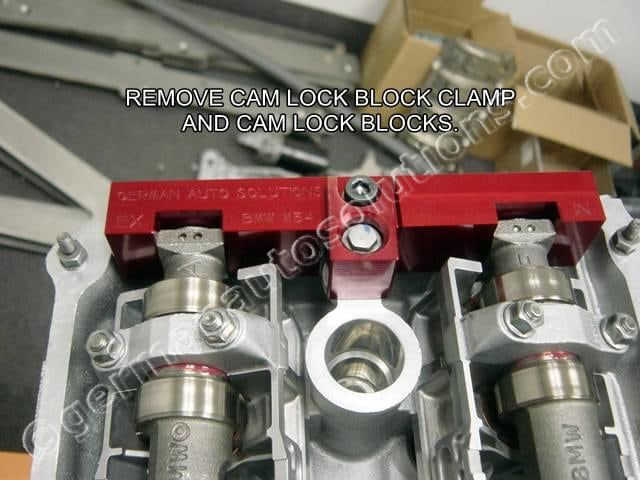
Remove the camshaft locking blocks.
#47
Remove the crankshaft TDC locking tool.
#48
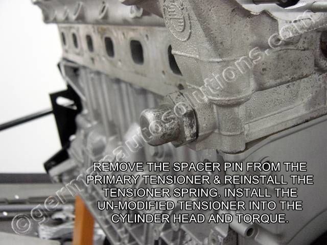
Remove the modified primary tensioner and replace the spacer pin with the spring (preferably a new one). Install the OEM tensioner into the cylinder head.
Use a new sealing washerand torque to 70Nm-52ft/lbs using a 32mm socket.
#49
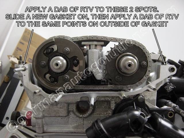
Apply some RTV gasket sealer to the two areas shown in the picture, install a new VANOS gasket over the studs and dowels, then apply some more RTV at the same locations on the outside face of the gasket.
I highly recommend Permatex “Ultra Grey” for all engine assembly applications where a RTV sealant is required.
#50
Remove the German Auto Solutions exhaust piston spacer from the VANOS unit, then slide the VANOS unit into place.
#51
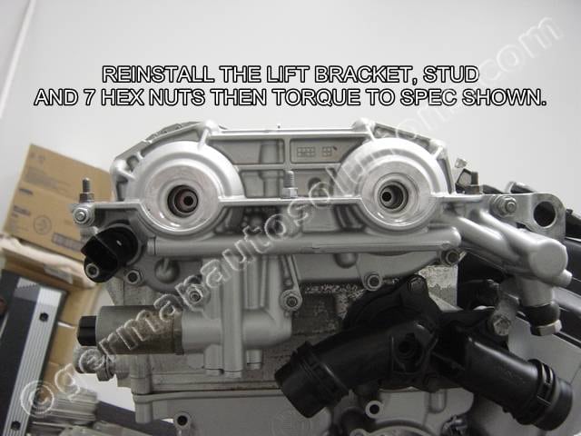
Install the OEM VANOS mounting hardware and lift bracket.
Torque the 6mm hex nuts to 10Nm-7.5ft/lbs, and the 8mm stud to 24Nm-18ft/lbs.
#52
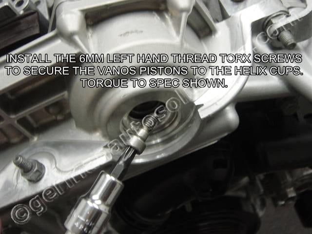
Install the 2 LEFT HAND THREAD torx head screws to secure the VANOS pistons to the helix cups.
I recommend a drop of medium strength threadlock here as well. Torque to 10Nm-7.5 ft/lbs.
#53
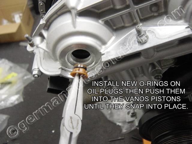
Locate the piston oil plugs.
The O-rings on these tend to harden and need to be replaced. BMW does not sell the O-rings for the plugs separately. New plugs with O-rings cost less than $2.00 each. I recommend just replacing the entire plug rather than trying to find O-rings that fit the used plugs.
Apply some oil or assembly lube to the O-rings then push the plugs into the VANOS pistons until they snap into place.
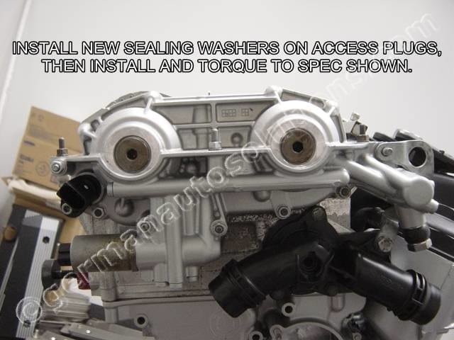
#54
Install new sealing washers on the access plugs then install and torque the plugs to 50Nm-37ft/lbs.
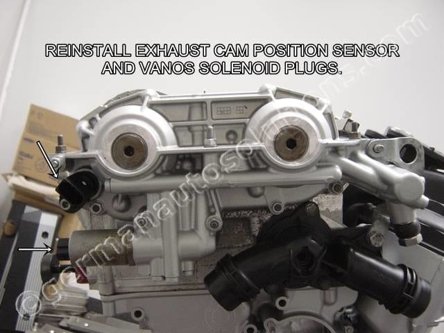
#55
Reconnect the exhaust cam position sensor plug and the exhaust VANOS solenoid plug.
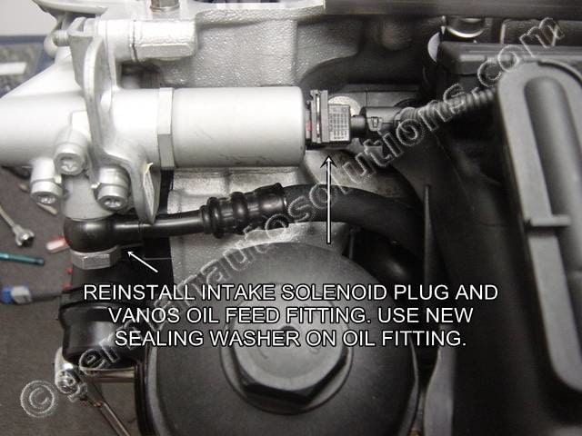
#56
Install the intake VANOS solenoid plug and the VANOS oil feed line. Use new sealing washers on the oil feed fitting. Torque the oil fitting to 32Nm-24ft/lbs.
You are now finished with the VANOS system timing and assembly.
Thank you for choosing quality US made German Auto Solutions Tools.