Instructions for the G.A.S. M54 DISA Repair and Upgrade Kit
The installation of the German Auto Solutions DISA repair & upgrade kit does not require any special tools, nor a high level of mechanical ability. The instruction presented here are very detailed and should allow anyone with basic mechanical skills to install the kit properly. We apologize to anyone with extensive mechanical experience who may think that these instructions are overdone to the point of explaining the obvious, but in order to be assured that someone with minor ‘Do it Yourself’ experience would have no trouble installing the kit we have gone overboard with detail and pictures
Please read the entire procedure through to the end to familiarize yourself with the process. It may seem like a lot of steps, but that’s only because there is so much detail provided. With the exception of cleaning your old DISA housing and removing the molded in housing seal, the entire procedure can be completed in about 15 minutes. If you cannot have a computer near by during the installation, please print off the PDF version of the instructions for reference before you begin.
Important!
This kit is NOT compatible with aftermarket DISA valves. Please verify that you have an OEM DISA valve before you begin the installation of this kit. An OEM BMW DISA valve will have one of the following part numbers on the main body of the unit – 7544806 or 7502269 for 2.5L versions, or 7544805 or 7502275 for 3.0L versions. It will also have the BMW logo just to the left of the part number.
Important!
Please check the parts list and make sure you have received everything with your kit. We go to great effort to make sure everything is packaged in the kit, but our shipping staff is human and can make a mistake. You don’t want to be half way through the install and find out that there is a problem.
Important!
Once you have removed the DISA valve from the vehicle, check the flapper valve that you received in the kit to make sure that it is physically the same size and shape as the one in your DISA. We have found several instances of 2.5L DISA valves having been installed into 3.0L vehicles by previous owners. If the size does not match, DO NOT start the kit installation. If the flapper valves are not the same size and shape you either have the wrong DISA valve in your vehicle or you may have ordered the wrong kit version. If you live in California and ordered a kit for a 2.5L vehicle and the new flapper is too small, you probably have the Ultra Low Emissions M56 engine which uses the 3.0L DISA Valve.
Mouse over images in the instructions to view full size
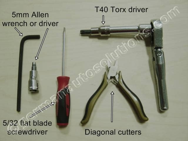
Tools Required to complete this kit installation:
T40 Torx driver
Small flat blade (5/32) screw driver.
5mm Allen (hex key) driver or wrench.
Small pair of diagonal cutters.
Optional – Small soft bristle stainless steel or brass wire brush.
Optional – Small 90 degree pick tool.
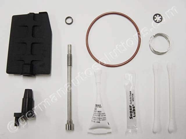
What comes in the kit:
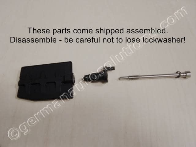
NOTE: The Flapper Valve, Pivot Screw and Bellcrank Lever come screwed together for shipping!
1 Tube of Locktite 262 threadlock. 1 Tube of synthetic grease. 1 Black twist tie. 1 Push on retaining clip. 2 cotton swabs
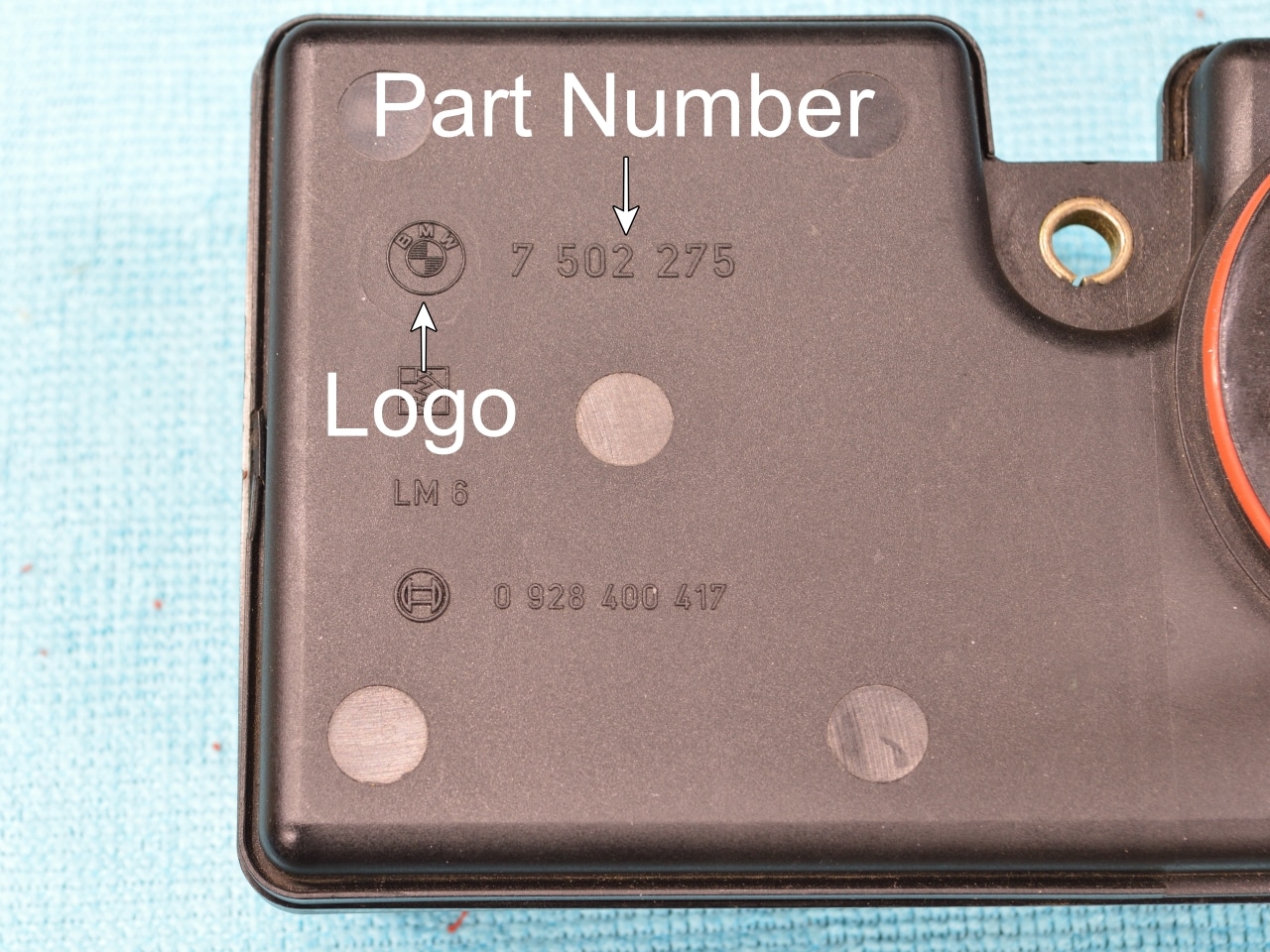
Before You Start!
Make sure that you are installing the kit into an OEM BMW or Rein brand DISA valve.
Refer to the image shown to verify that your DISA valve has BOTH the BMW logo and the BMW part number on the body of the DISA valve housing. If not, it is not an OEM DISA valve. There are 4 different BMW part numbers, so your part number does not need to match the part number in the image. Our kit only fits OEM BMW and Rein brand DISA valves. If you do not have an OEM BMW or Rein brand DISA valve, do not continue with the kit installation. Rein brand DISA valves have no markings. The only way to know if you have a Rein brand DISA valve, is if you purchased it yourself. NOTE – The Rein DISA valve requires a different kit. If you have a Rein DISA valve, make sure that you purchased the kit for the Rein brand DISA.
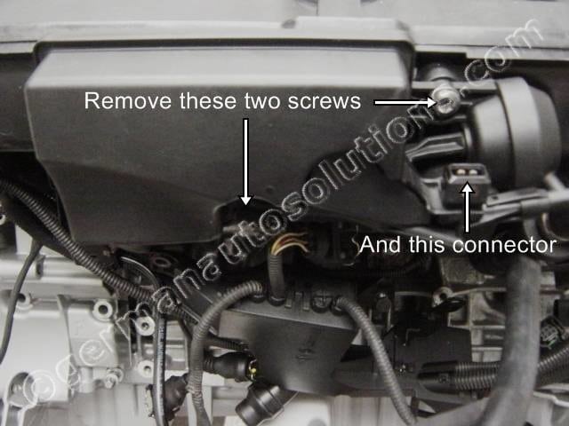
#1
Start by removing the old DISA unit from the intake manifold by removing the two T40 Torx screws and one electrical connector securing the DISA.
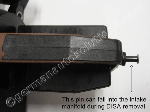
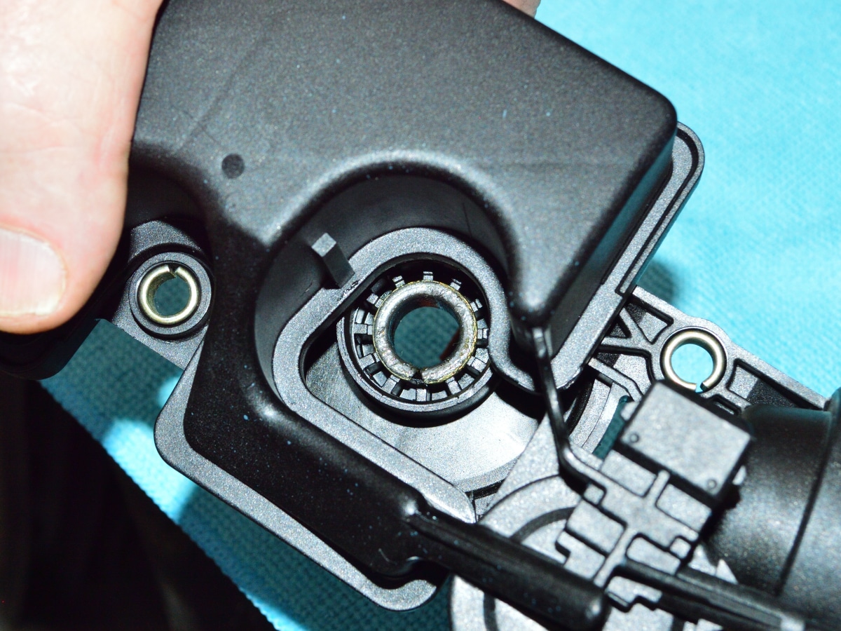
SLOWLY pull the DISA from the manifold. There is a steel pin in the end of the DISA housing (shown partially removed in the next picture) that can come loose and fall into the manifold during removal. Make sure that the pin is still in place on your DISA after removal.
If not, Do not start the engine again until the pin is located!!!!!!!!!!!!
#2
Make sure that this pin is still in the DISA after removal. If not, it has probably fallen into the intake manifold as you removed the DISA. If the pin has fallen into the manifold it should be able to be easily retrieved through the DISA opening in the manifold. DO NOT proceed until you locate this pin.
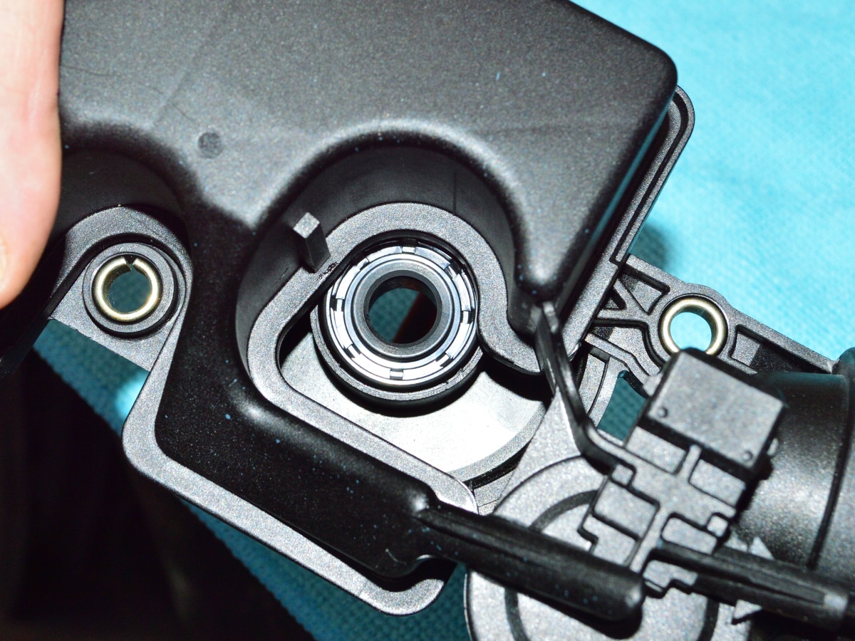
Note: The pin in this picture is show partially pulled out from its normal position. If your pin is still tightly seated into the flapper valve you will only see the flat head of the pin sitting flush with the end of the support bearing, as shown in picture #6.
I’m sorry to be a nag for repeating the next two paragraphs from the beginning of the instructions, but in every instance where there has been an issue with someone receiving the wrong size kit for their DISA valve, they did not notice it until they had their DISA valve torn apart. Once your DISA valve has been disassembled, depending on its condition, it may not be able to be reassembled. This can end up being a great inconvenience if it causes you vehicle down time. Before you start this procedure please take the time to read the following two paragraphs.
Important! Please check the parts list and make sure you have received everything with your kit. We go to great effort to make sure everything is packaged in the kit, but our shipping staff is human and can make a mistake. You don’t want to be half way through the install and find out that there is a problem.
Important! Once you have removed the DISA valve from the vehicle, check the flapper valve that you received in the kit to make sure that it is physically the same size and shape as the one in your DISA. We have found several instances of 2.5L DISA valves having been installed into 3.0L vehicles by previous owners. If the size does not match, DO NOT start the kit installation. If the flapper valves are not the same size and shape you either have the wrong DISA valve in your vehicle or you may have ordered the wrong kit version.
#3
Before beginning the installation of the kit you will what to make sure that your DISA vacuum pot is in good working order. This is a very low failure item, but it’s always best to check it anyway. The test will confirm that your vacuum pot does not have a vacuum leak. The next step will tell you how to perform the test and what to look for.
If your DISA flapper valve is worn & flops around loosely you will not be able to perform this test since closing the flapper valve will not move the vacuum pot lever. If this is the case with your DISA, I’ll show you an alternative way to test it when you get to step #11.
#4
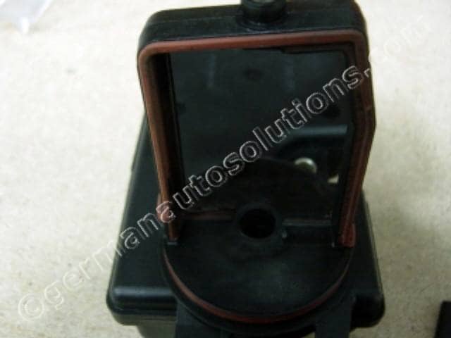
To test the vacuum pot:
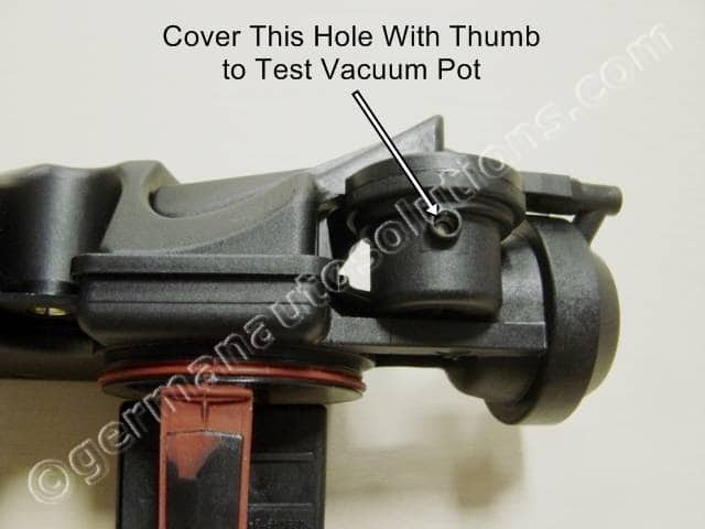
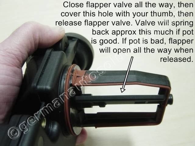
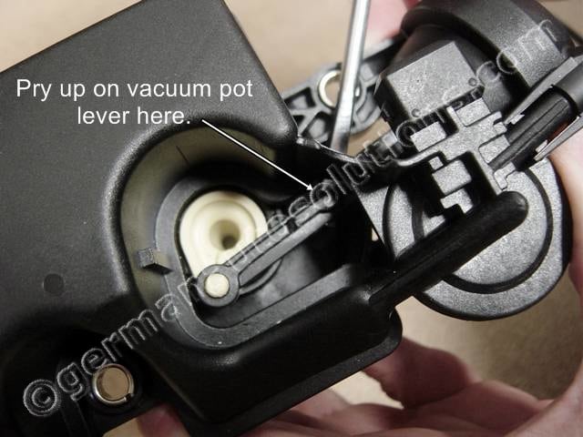
Manually close the flapper valve until it’s seated against the rubber seal inside the support frame.
Cover the hole shown with your thumb while valve is closed.
Release the flapper valve and see what happens.
If your vacuum pot is good, the valve will spring open approximately what’s shown in the picture and stop. If the vacuum pot is bad the valve will spring open all the way.
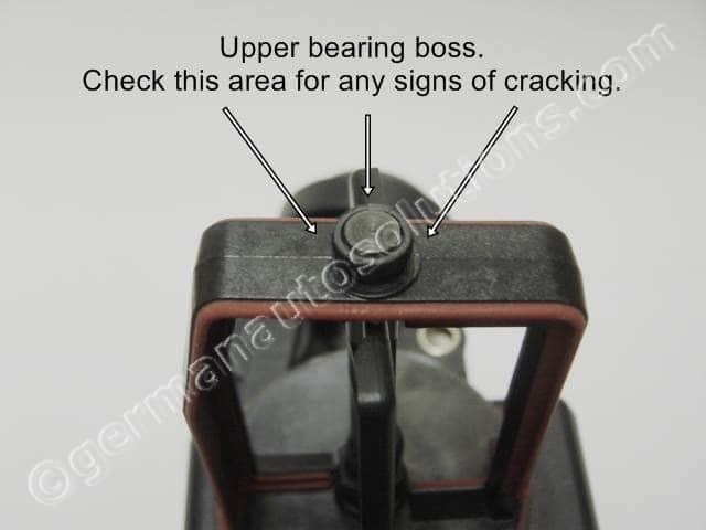
#5
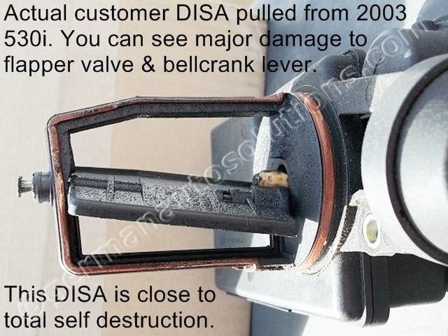
The last thing to check before installing the kit is the frame and bearing boss. On rare occasions when there is extreme wear like what’s shown in the picture, the flapper valve can come completely loose from the part of the mechanism that controls its movement. If this happens the flapper valve can bend back and forth inside the intake manifold and damage or crack the upper bearing support.
Clean around the area shown in the next picture and check for any signs of cracking.
#6
Both vacuum pot and cracked bearing support failures are rare, but we would rather be sure that you are repairing a serviceable DISA and are happy with the finished results of the repair. Remember, if your DISA valve is not repairable, & you decide to purchase a new one, the kit is returnable for a full refund less shipping charges. If you end up needing a new DISA valve, we highly recommend that you use your refund to trade up to the G.A.S. DISA Gold Valve.
If you’ve determined that your DISA valve is serviceable you can now proceed to the installation of the kit.
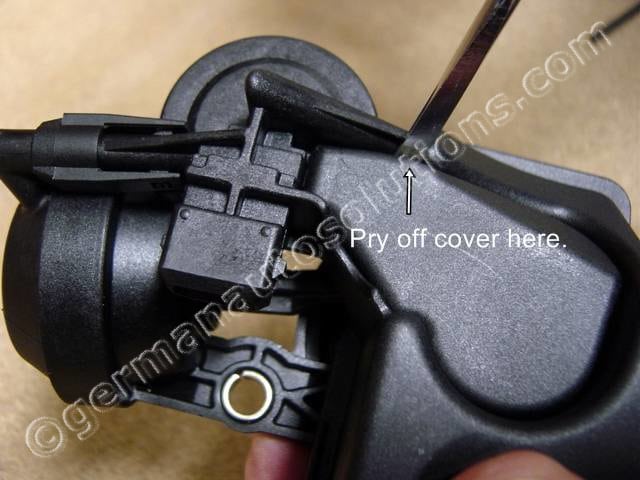
#7
The installation begins by removing the actuator access cover. You’ll need a small flat blade screwdriver. Push in and pry up at the location shown. The cover pops off easily.
#8
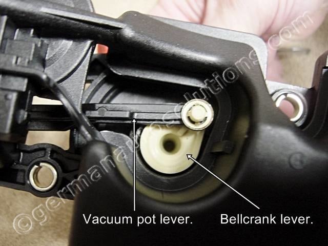
This is what’s under the cover.
The creme colored piece is the bell crank lever which rotates the flapper valve. This is the piece that typically wears out and causes most of the problems.
The black piece is the lever that connects the vacuum pot diaphragm to the bell crank lever.
#9
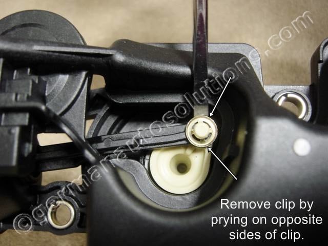
Next you need to remove the retaining clip that holds the vacuum lever onto the bell crank lever. Work the clip off by prying up under clip with a small flat blade screwdriver. Alternate prying up on opposite sides of the clip until you have worked the clip off.
There is a new clip in the kit so you don’t need to worry about damaging the stock one.
#10
After removing the clip you can pop the vacuum lever off of the bell crank lever. Using a small flat blade screwdriver at the location shown, pry up the vacuum actuator lever until it pops off of the pin on the bell crank lever.
If your unit is badly worn you may need to hold the creme colored bell crank lever in place so that it doesn’t try to lift up when prying up the vacuum lever.
#11
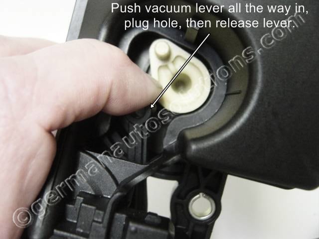
NOTE: This step is required ONLY if you could not test the vacuum pot in step #4 due to excessive wear. If you have already tested the vacuum pot, proceed to step #12.
To test the vacuum pot the alternate way, push the vacuum lever all the way in with your finger, cover the hole from step #4, then release the lever while keeping the hole covered. If the vacuum pot is good the lever will spring back about half way then stop. If the vacuum pot is bad, the lever will spring back all the way.
#12
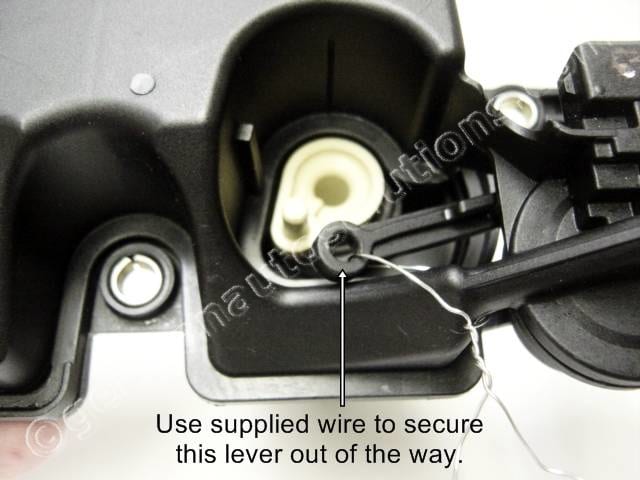
Using the supplied safety wire, (Current kits are now shipped with an eight inch twist tie), secure the vacuum lever off to the side to keep it out of the way. This is not a necessary step but is very helpful.
#13
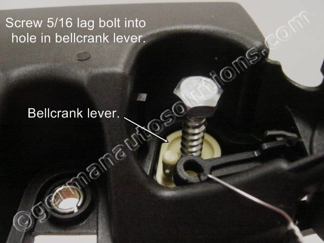
Next you will be removing the bell crank lever from the housing. Start by screwing the supplied 5/16 lag bolt into the hole in the bell crank lever as shown. If you don’t have a 1/2 inch or 13mm wrench or socket, this can easily be accomplished with a pair of pliers.
Note the installed height shown and refer to the next picture as well. You will not be screwing the bolt all the way in. Just one full turn is sufficient.
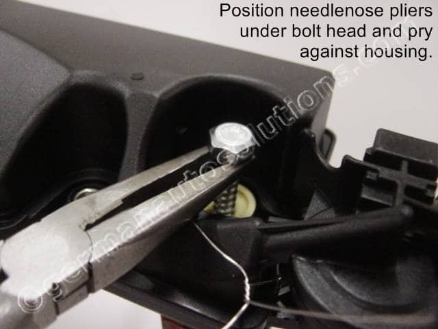
#14
You will want to screw the bolt in just to a depth that will allow you to get a pair of pliers (preferably needle nose) under the bolt head in the position and and at the angle shown.
Once you have the bolt screwed in to the proper depth, use the pliers to pry against the housing and pop the bell crank lever up. If you have a new DISA, or one that’s in very good shape, this will take a little force. If you have a badly worn DISA, you will probably be able to pull the bell crank lever out by hand.
#15
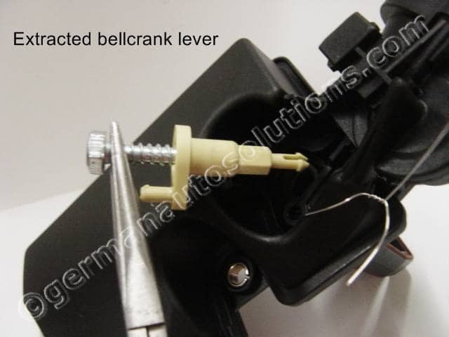
This is what the extracted bell crank lever looks like.
This is a new one, a badly worn one will look very different depending on how much plastic has been worn away.
#16
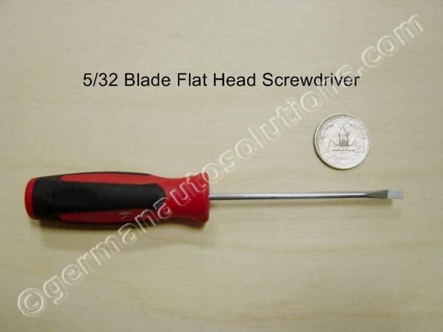
This is a Picture of the proper size screwdriver to be used in the next step for your reference.
It’s not rocket science, just use a quality screwdriver with a blade that will fit into the spot shown in the next step.
#17
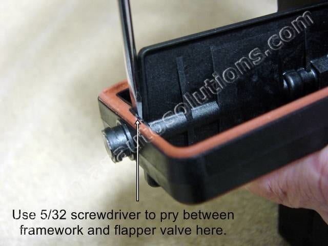
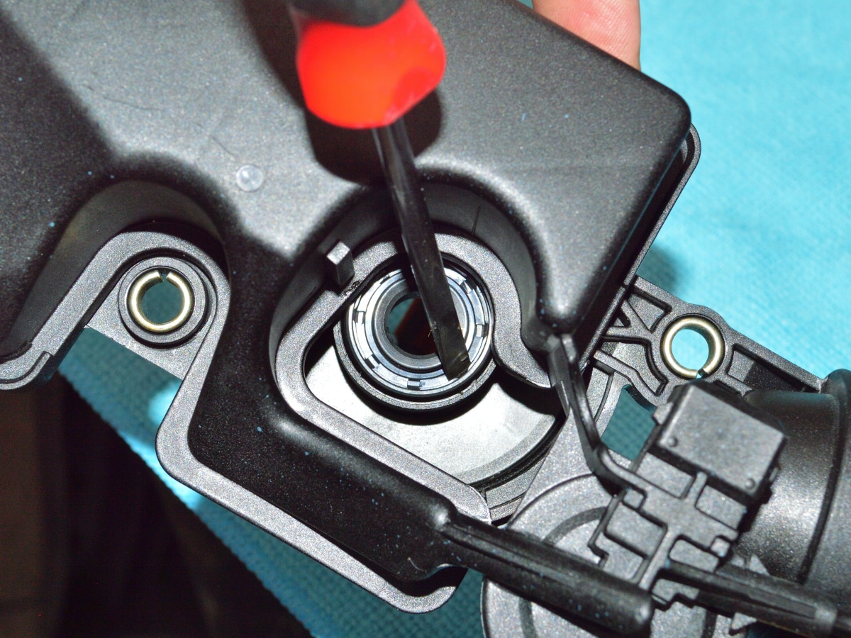
The next step is to remove the pressed in steel pin.
This is a critical procedure if your DISA is new or the pin is still fully seated in the flapper valve. The pin head is very thin and sits flush with the top of the support bearing, so there isn’t an easy way to grab it.
You need to get a proper size screwdriver blade that just fits between the top edge of the flapper valve and the underside of the framework at the location shown. Position the blade so when you twist the screwdriver, it will pry up on the framework.
A used DISA may have the pin already falling out. If you have one with the pin fully seated, be careful not to damage the framework. See the next step before prying.
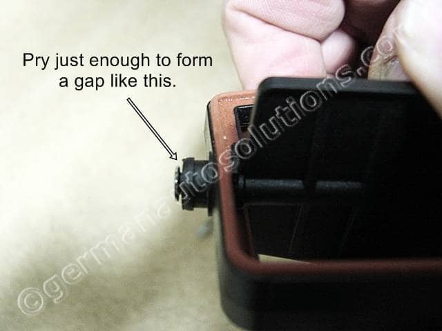
#18
This is what the pin head should look like after prying up on the framework.
You need only pry enough to form a gap under the head.
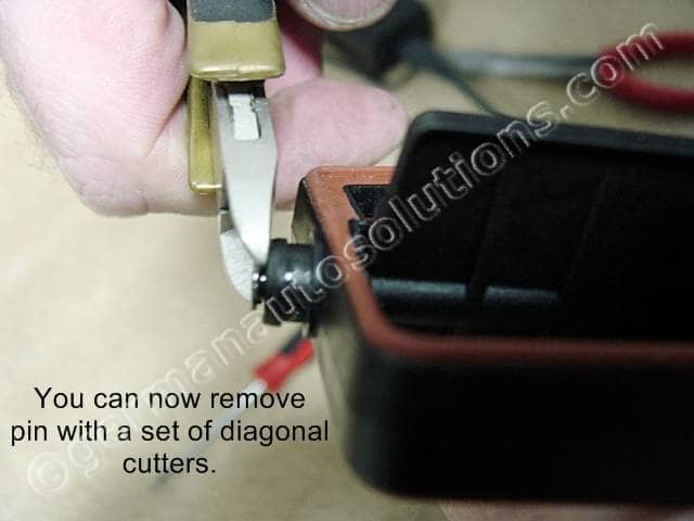
#19
Now you can remove the pin with a small pair of diagonal cutters.
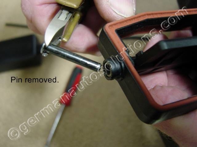
#20
Here is the steel pin removed.
It’s pressed in pretty tightly on a new unit.
This is what has ruined a few engines after it fell out and went through the intake runner and into the combustion chamber.
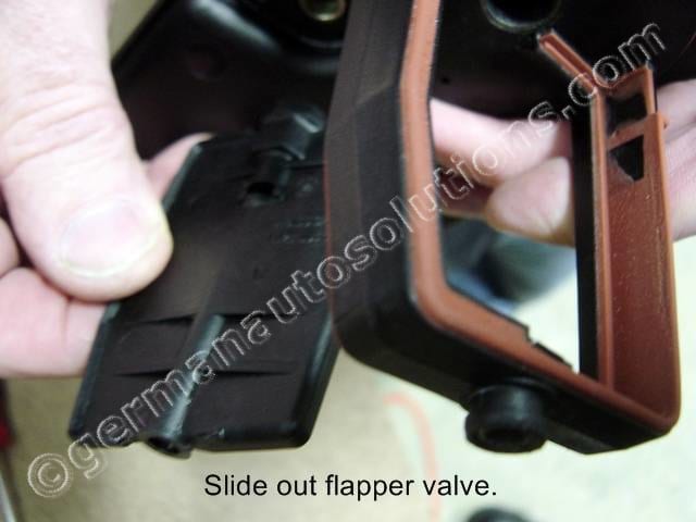
#21
Once the steel pin has been removed, the flapper valve can be slid out of the DISA housing frame work.
#22
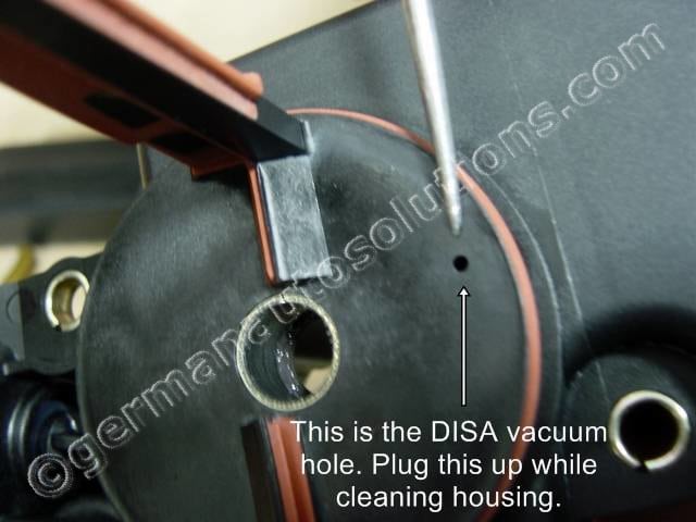
Now that you have the DISA disassembled you will want to clean the DISA housing. I recommend using a full strength industrial cleaner like Simple Green or Purple Power from Auto Zone. I would avoid brake cleaner or solvents as they can make the plastic brittle.
Note the little hole pointed to in the picture, this is the vacuum port that actuates the DISA. Plug this with a tooth pick or something to avoid getting water into the chamber.Use a tooth brush and cleaner and work at it until it’s acceptably clean to you. If you plugged the little vacuum hole, don’t forget to remove the plug after you’ve finished cleaning.
#23
Now that it’s all cleaned up, give it one more visual inspection for signs of damage.
Cracked or broken plastic is bad, worn or small missing sections of the orange rubber seal is OK.
If you did not purchase the optional bellcrank seal, please skip to step #29
#24
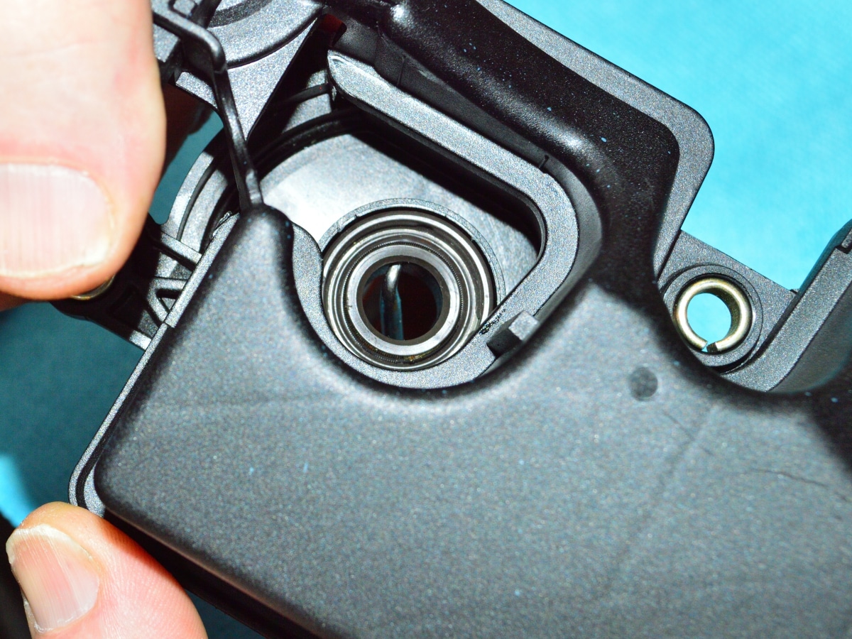
If you are replacing the bellcrank seal, you need to start by removing the old seal. The best tool for that is a 90deg pick tool. If you do not have a pick tool, the next step shows how to remove the seal with a small flat blade screwdriver.
When using a pick tool, as shown in the image, you position the bent end of the pick in the small gap between the Teflon bearing and the back of the seal. Once the pick is properly positioned, press firmly to dislodge the seal from the housing.
#25
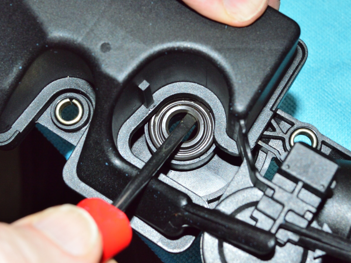
You can also remove the seal with a small flat blade screwdriver. In this case, insert the blade of the screwdriver just under body of the seal as shown in the image. Press firmly inward while prying up on the seal.
#26
Once the seal has been removed, clean up the pocket area that the seal was removed from.
#27
Place the new seal over the pocket with the spring lip side of the seal facing you as shown. Press the seal into the pocket using your thumb. You will most likely not be able to fully seat the seal this way. See the next step for instructions on how to fully seat the seal.
#28
To fully seat the seal, place the blade of a small screwdriver up against the the rim of the seal as shown. Press down firmly against the seal while making sure that the blade of the screwdriver is against the outer edge of the rim of the seal. Do not press near the spring lip portion of the seal. Work your way around the seal using this technique until the seal is fully seated into the housing.
#29
This is the beginning of the installation phase of the kit.
The valve, bell crank lever, & custom pivot screw are shipped assembled. Now is a good time to dis-assemble them.
Using a 5mm hex wrench, unscrew the pivot bolt and dis-assemble the new parts. NOTE: The picture shows a lock washer on the pivot screw. It is now shipped with the kit accessories in the separate zip lock bag to reduce the possibility of it becoming lost during disassembly.
#30
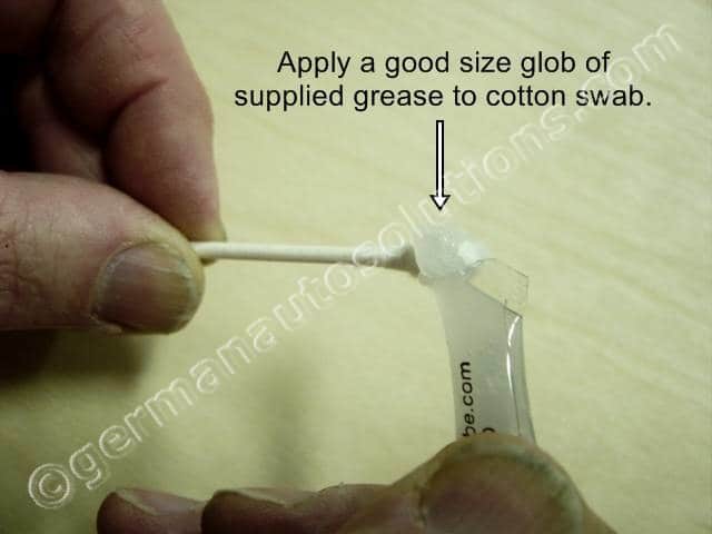
The first part of assembly involves lubing and installing the new bell crank lever.
Start by applying a nice glob of the supplied grease to one of the supplied cotton swabs.
#31
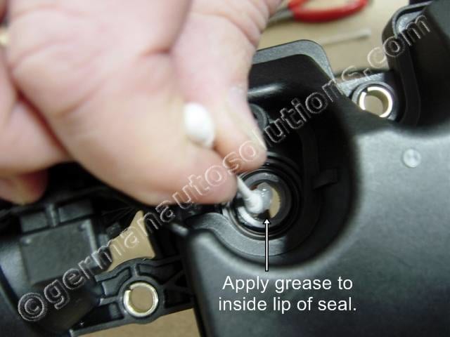
Apply the grease to the inner lip of the bell crank seal as shown.
Spread it around inside the lip of the seal. Avoid leaving any cotton swab fibers inside of the bearing area.
#32
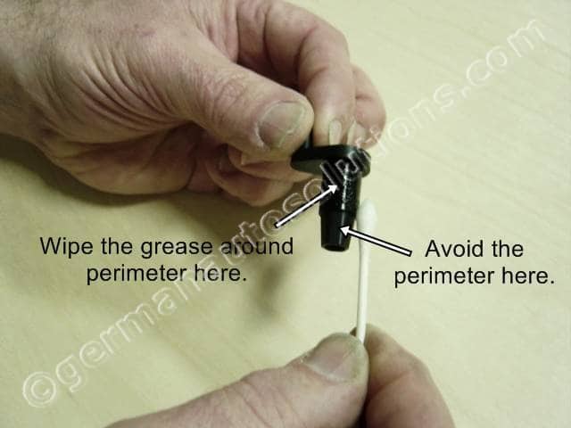
Next apply some grease to the middle section of the bell crank lever as shown.
Spread it around the outside and avoid the tapered hex shaped section.
Note: The picture shows applying the grease to the lever using a cotton swab. I currently apply the grease with my figure instead. This avoids the possibility of leaving cotton fibers on the bearing surface of the lever that may cause the lever to bind up in the DISA housing bearing.
#33
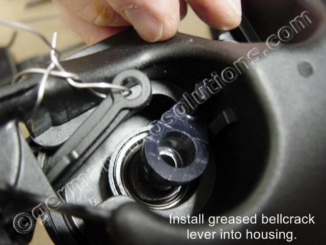
Note the rotational alignment of the bell crank lever as shown and insert the new lubed up lever into the DISA housing.
Push the lever all the way in.
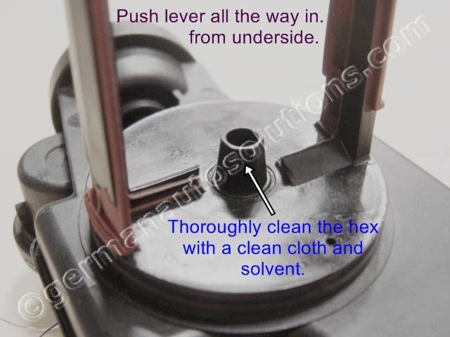
#34
Push the lever all the way in as far as it will go. It should look like this and will probably have some grease on the tapered hex section from pushing it through the bearing.
While keeping the bell crank pushed in with your finger from the opposite side, completely clean the protruding hex taper with a clean cloth and solvent. Use brake cleaner, acetone, or similar solvent.
#35
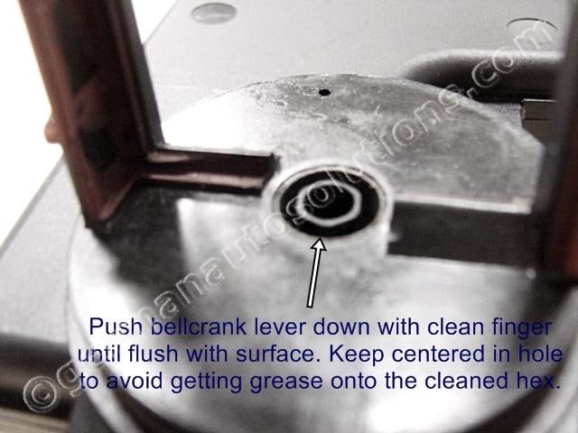
Next, with a clean finger, push the bell crank back down until it’s flush with the surface as shown.
Be careful, the goal is to keep the tapered hex portion centered in the hole so that you don’t get any grease on the taper again.
The seal will hold it centered in place once it’s pushed down.
#36
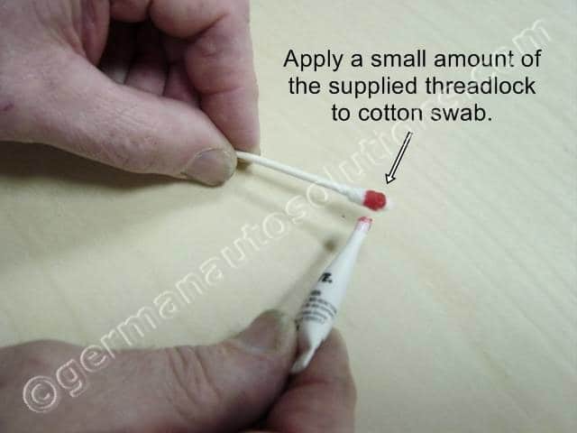
Next we are going to be installing the new flapper valve.
Begin by applying a small amount of the supplied threadlock to the end of a new cotton swab.
#37
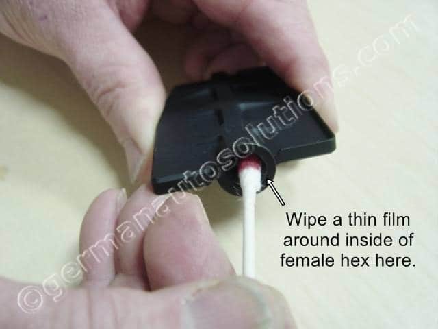
Now wipe a thin film inside the female hex pocket of the new flapper valve.
Don’t over do it, it should just be lightly wet on the sides. You don’t want excess that will wick into the bearing during assembly.
Note: The next 9 steps, up through step # 41, need to be performed within about 10-15 minutes of applying the threadlock in this step. 10 minutes is plenty of time so there is no need to rush.
#38
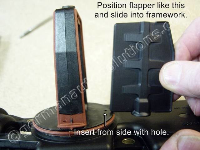
Now you can slide the new valve into place.
This is the only orientation that will allow the valve to slide in due to it’s shape. It goes in from the side with the vacuum hole and with the valve positioned as shown.
It’s designed to be a precision fit so it needs to be straight in order to slide in.
#39
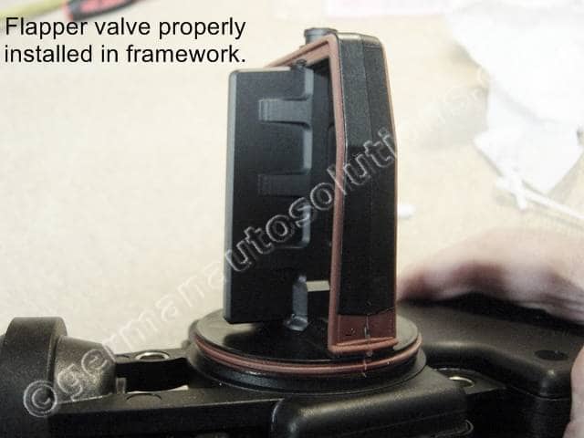
View of the new flapper valve properly in place.
Center the flapper to the opening in the top support bearing.
#40
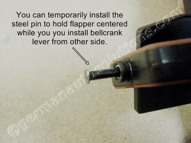
Next you will be pushing the bell crank lever into place.
If you want you can temporarily replace the steel pin and hold it in with your finger while you push the bell crank lever into place. This is not necessary, but it helps to keep that end centered while working on the other end.
#41
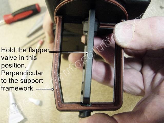
You will need to position the flapper valve properly before pushing the bell crank lever into place.
This is the position you want the flapper valve to be in, 90 degrees (perpendicular) to the support framework.
You will need to hold the flapper valve in this position for the next step.
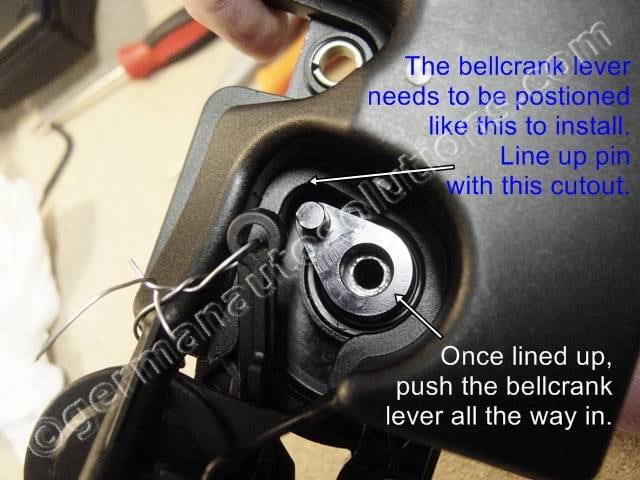
#42
Next, make sure that the bell crank lever is still aligned like this and that the flapper valve is perpendicular to the support framework, then push the lever into place as far as it will go.
#43
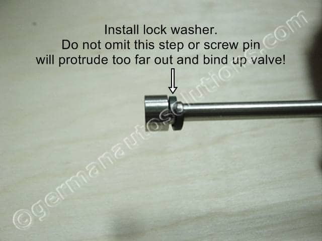
You will now prepare the new pivot screw for installation.
Install the supplied lock washer onto the new pivot screw. Do not miss lock washer or the pin will protrude too far through the other end of the housing and bind everything up.
The washer is there to provide a hardened surface between the screw head and the aluminum valve during tightening of the screw.
#44
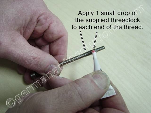
Apply a drop of the supplied threadlock to each end of the threaded portion of the pivot screw.
Do not over do it. The next picture will show the proper amount to apply.
#45
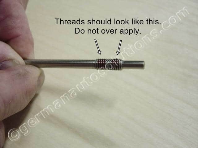
Anything more than this is unnecessary.
Excess theadlock could try to make it’s way into the end bearing so don’t feel the need to over do it.
#46
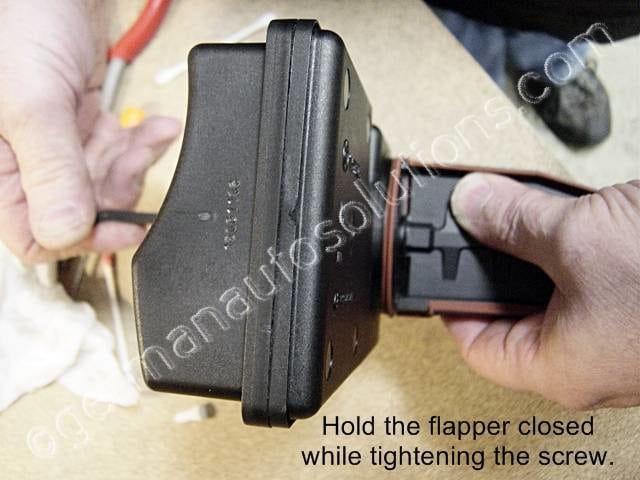
You can now install the pivot screw.
Looking down the end of the support bearing hole will help with aligning the pin of the pivot screw with the bearing hole. After lightly snugging the screw you will want to hold the flapper toward the closed position while fully tightening. This prevents you from applying tightening pressure to the DISA frame or mechanism.
Tighten the screw with a 5mm Allen wrench or hex driver. You want the screw very tight to fully seat the tapered surfaces together. Once the screw is tight, make sure the valve will rotate back and forth without binding. Some resistance is normal due to the drag of the bearing seal, but the flapper should rotate smoothly from opened to closed.
#47
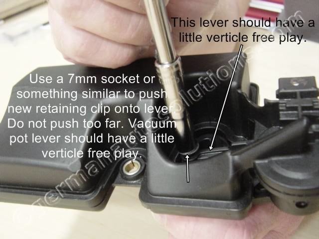
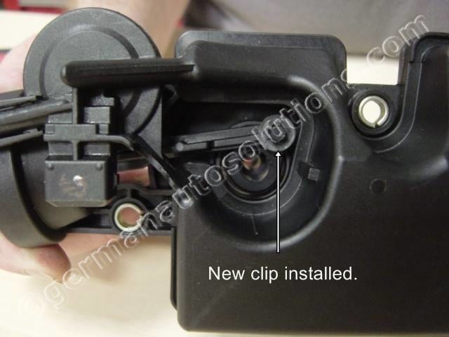
You can now put the vacuum pot actuator lever back over the pin of the new bell crank lever and push the new retaining clip on.
Use a socket or other similar tool to push the clip onto the pin.
DO NOT push the clip on as far as it will go. Go slowly, you want the vacuum lever to have a little bit of vertical free play.
If you push it on too far it’s difficult to pull it back again. You can try lightly grabbing the clip with a pair of needle nose pliers while pulling and twisting the clip.
#48
Double check that the flapper valve can be rotated to the closed position and back open without binding. If you manually close the valve, then release it, the valve should spring back to the fully open position, except as noted below.
Note: The internal rubber boot of the vacuum pot has a tendency to kink when the valve is manually closed. This kinking may occasionally cause the valve to not spring back to the fully open position when manually closed and then released. This is normal and does not happen in the vehicle when the valve is actuated by vacuum. If the mechanism did not show any signs of binding in step #41, you have nothing to be concerned about.
#49
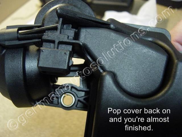
You can now reinstall the plastic cover and you’re finished with the valve portion of the install.
#50
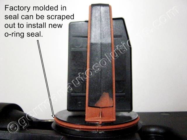
Now that the new valve assembly is installed, all that is left is to replace the main housing seal.
The M54 has the main seal molded into the framework which is why BMW doesn’t offer a replacement O-ring. The old seal needs to be scraped out.
#51
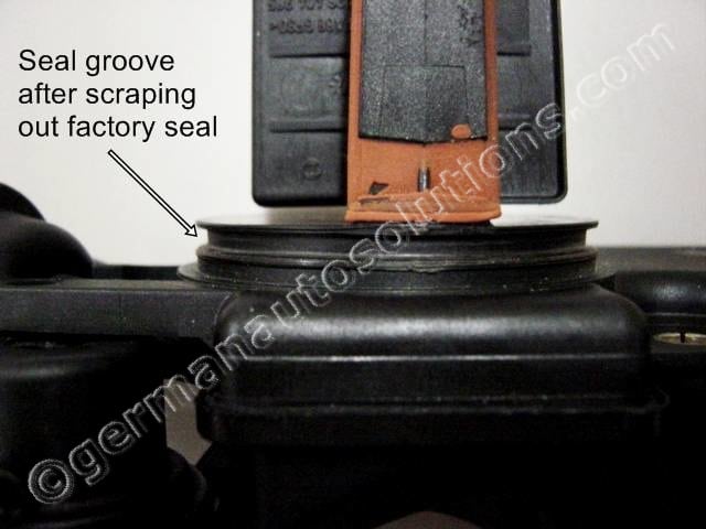
I have found the best tool to remove the factory seal to be a small 90 degree pick tool.
These are available from Harbor Freight, Sears, Snap-on, etc. If a pick tool is not available, a small flat blade screwdriver will work reasonably well. After scraping the molded silicone out, you can use a fine-wire stainless steel or brass brush (Harbor Freight) to remove the little remnants. A little piece of Scotchbrite or steel wool can also be used instead of a brush.
The groove should look like this when you’re finished. Be careful not to scratch or gouge the groove. This can be a time consuming process if your molded seal is in good condition. If you are retrofitting a new DISA you can skip this step and keep the new O-ring for later replacement if needed.
#52
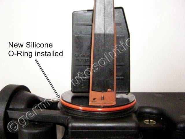
Once the groove is cleaned you can install the new O-ring.
Squeeze some of the supplied grease onto your fingers, then work the grease onto the surface of the O-ring before installation. This not only helps ease the reinstallation of the DISA housing into the intake manifold, but also aids in sealing.
Wipe a film around the I.D. of the manifold opening as well. We recommend waiting 12 hours before use to allow time for the threadlock to cure.
#53
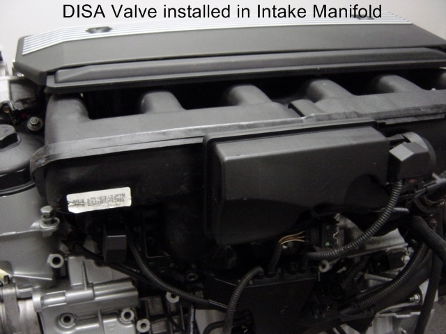
When re-installing the DISA housing into the intake manifold, push the housing in until the new O-ring contacts the manifold opening, then tighten the 2 torx screws just finger tight. Now tighten the screws, alternating one turn at a time with the wrench to draw the DISA into the manifold evenly. Do not over tighten.
Congratulations, you have now completed the DISA repair kit installation.
Thank you for purchasing American made German Auto Solutions Products.