****** IMPORTANT - IMPORTANT - IMPORTANT - IMPORTANT - IMPORTANT ******
****** Read all three sections marked 'IMPORTANT' before you begin ******
This DIY guide is only recommend for people with a reasonable amount experience wrenching on cars and with access to professional quality tools. I HIGHLY recommend that you completely read through the entire instructions several times before you begin to familiarize yourself with procedure. If you don’t feel comfortable with any part of these instructions please do not attempt this project on your own.
If you cannot have a computer nearby during this procedure, print off these PDF instructions. I highly recommend using a laptop computer at the vehicle location if available over using the printed PDF instructions. The ability to enlarge the pictures on a computer display will ensure that all the important detail information in the pictures will be visible.
DO NOT attempt to perform these instructions using a Smart Phone! The pictures contain important details that would be very difficult to view properly on the small display of a smart phone.
Make sure that you read each step fully from beginning to end before you perform any part of a step. Some steps may contain multiple procedures, and some steps contain information at the end of the step, that is crucial to completing the step properly.
****** IMPORTANT INFORMATION ABOUT THE REMOVAL OF THE INTAKE MANIFOLD ******
The German Auto Solutions CCV System can be installed with or without removing the intake manifold. This DIY guide provides instructions on installing the CCV System without the removal of the intake manifold. If you prefer to remove the intake manifold you will need to consult a shop manual or one of the many internet forums threads covering OEM CCV replacement.
There are two advantages to removing the intake manifold to physically remove the OEM CCV, neither of which I think justifies the additional amount of work involved. First, by removing the OEM CCV you will by removing an insignificant amount of weight (a couple of ounces) from your BMW, and second, you gain much easier access to the dip stick tube area for cleaning and removal of the dip stick tube and installation of the drain back hose.
If you follow these instructions and leave the OEM CCV screwed to the bottom of the intake manifold it will IN NO WAY remain connected to your new G.A.S. CCV or any other part of the engine. We chose to provide our instructions without manifold removal to make the procedure simpler for use by people with a wider variety of skill levels.
If you have the time and the skills and prefer to remove the intake manifold, go for it, I have no reason to discourage it.
****** IMPORTANT INFORMATION ABOUT THE OEM DIP STICK TUBE ******
There are two versions of the M54 dip stick tube, the one that came stock on the vehicle and the cold climate version. The original equipment dip stick tube has a ‘tube within a tube’ construction where the CCV drain back hose attaches. The cold climate version has a ‘single tube’ construction. BMW came out with the cold climate version of the dip stick tube to address the problem of the CCV drain back portion of the tube clogging up in cold weather.
If your original equipment dip stick tube isn’t clogged it can be reused, although it is highly recommended that it is replaced with the cold climate version. Using the cold climate dip stick tube allows full use of the optional drain back hose cleaning wand. The wand is designed to clean all the way thru the 90 degree bend in the dipstick tube and into the center chamber of the tube. When using the original equipment dip stick tube the cleaning wand will bottom out against the wall of the ‘tube within a tube’ and prevent the wand from cleaning the entire drain back path.
The BMW part number for the cold climate dip stick tube is 11437565437
Tools Required to Complete These Instructions:
3/8″ drive metric socket set.
36mm socket with ratchet to fit.
T25 torx driver or 3/8″ drive torx bit.
5mm hex wrench or 3/8″ drive hex bit socket.
#2 Phillips head screwdriver.
Large diagonal cutters or hose clamp crimping tool. (See step #37)
NOTE: This tool list only covers the actual installation of the G.A.S. CCV. There may be other tools required for vehicle disassembly that are not listed here because they are vehicle model dependent.
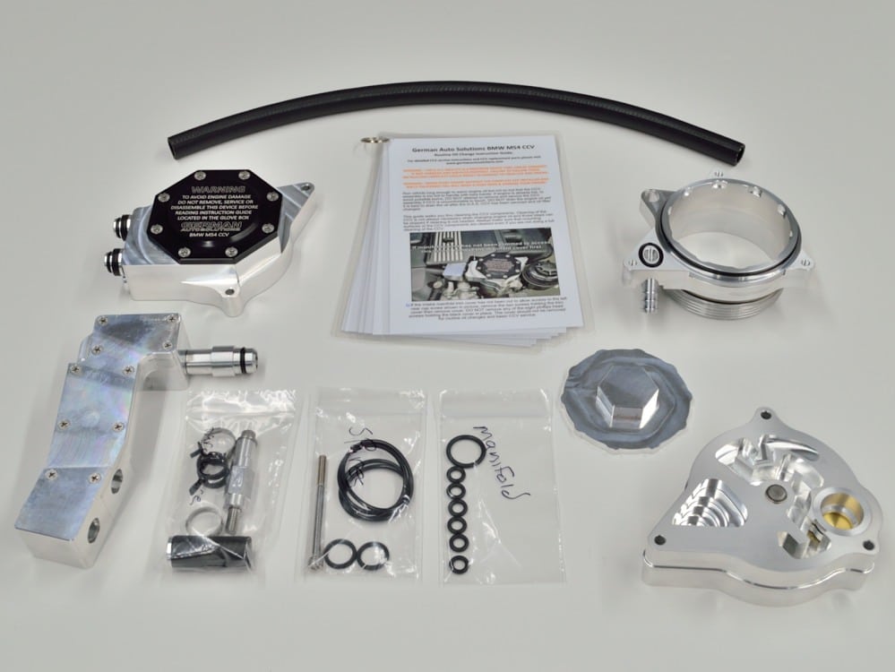
This is what comes in the German Auto Solutions CCV System Kit.
Make sure that you have everything pictured here before you begin.
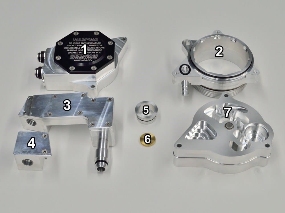
The main components of the German Auto Solutions CCV Kit.
Vacuum Regulator Assembly.
CCV Mounting Base.
Main Docking Manifold.
Docking Manifold Extension.
Oil Separator Drain Sleeve.
Drain Sleeve Check Valve.
Oil Separator.
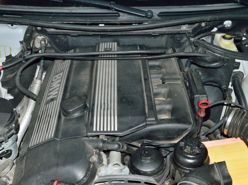
The first section of these instructions involves removing trim panels, air box and other necessary items required to install the German Auto Solutions CCV Kit.
The vehicle shown here is a E46 330i. This initial procedure for other BMW models will vary.
#1
Start by removing the old DISA unit from the intake manifold by removing the two T40 Torx screws and one electrical connector securing the DISA.
SLOWLY pull the DISA from the manifold. There is a steel pin in the end of the DISA housing (shown partially removed in the next picture) that can come loose and fall into the manifold during removal. Make sure that the pin is still in place on your DISA after removal.
If not, Do not start the engine again until the pin is located!!!!!!!!!!!!
#2
Start by unhooking the clips that hold the air box cover in place then remove the cover.
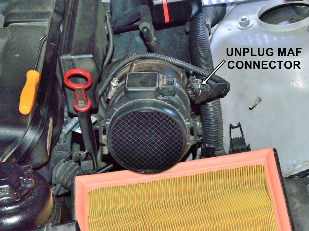
#3
Unhook the connector to the Mass Air Flow sensor.
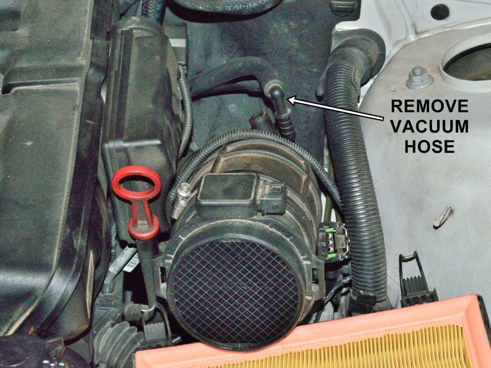
#4
Pull the hose and 90 degree fitting from the rubber intake boot as shown.
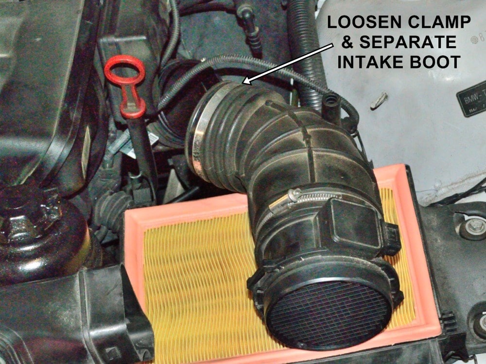
#5
Loosen the hose clamp then separate the Mass Air Flow sensor and rubber boot.
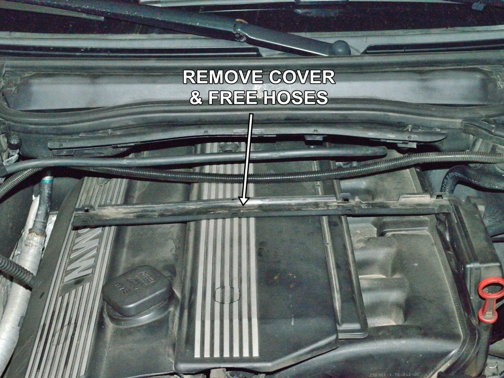
#6
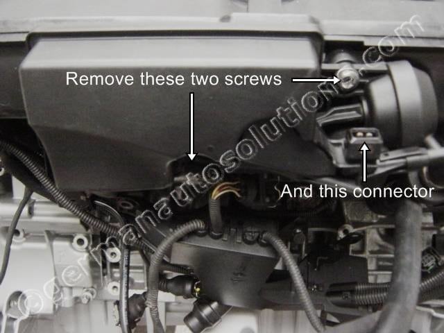
Remove the plastic cover that holds the wiring loom and hose from the front of the cabin air filter housing then drop the wiring loom and hose out of the way.
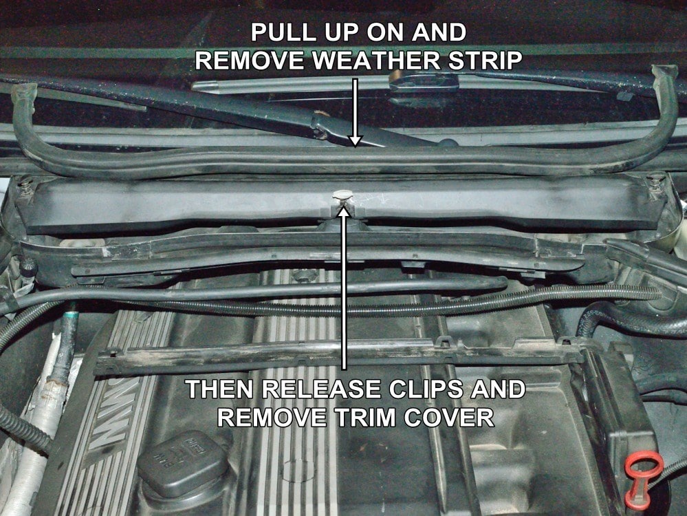
#7
Pull up to remove the rubber weather strip surrounding the cabin air filter housing.
Twist to release the three captive fasteners holding the metal trim panel then lift it out.
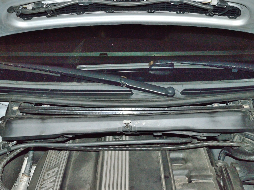
#8
Trim panel removed.
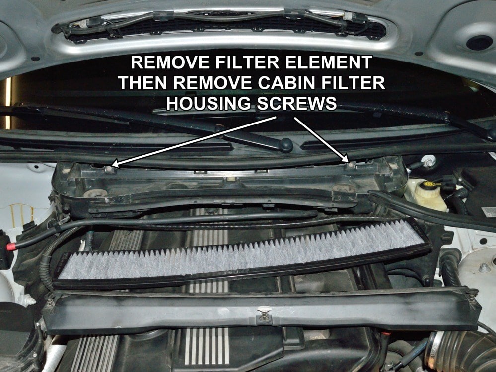
#9
Slide out the cabin air filter element then remove the screws holding the cabin air filter housing in place.
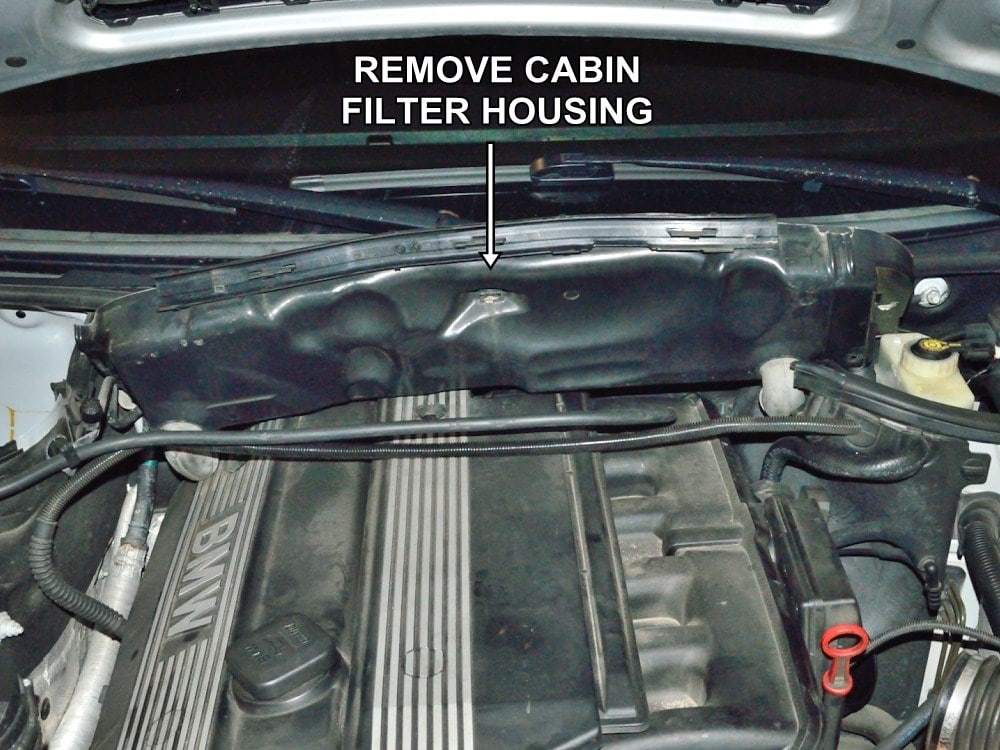
#10
Remove the cabin air filter housing.
#11
Cabin air filter housing removed.
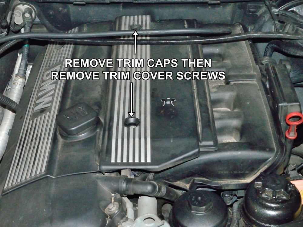
#12
Remove the trim caps over the two intake manifold trim cover screws then remove the screws.
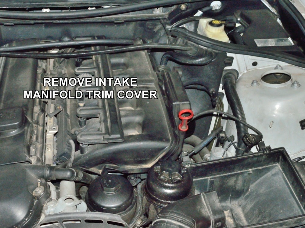
#13
Lift off the intake manifold trim cover.
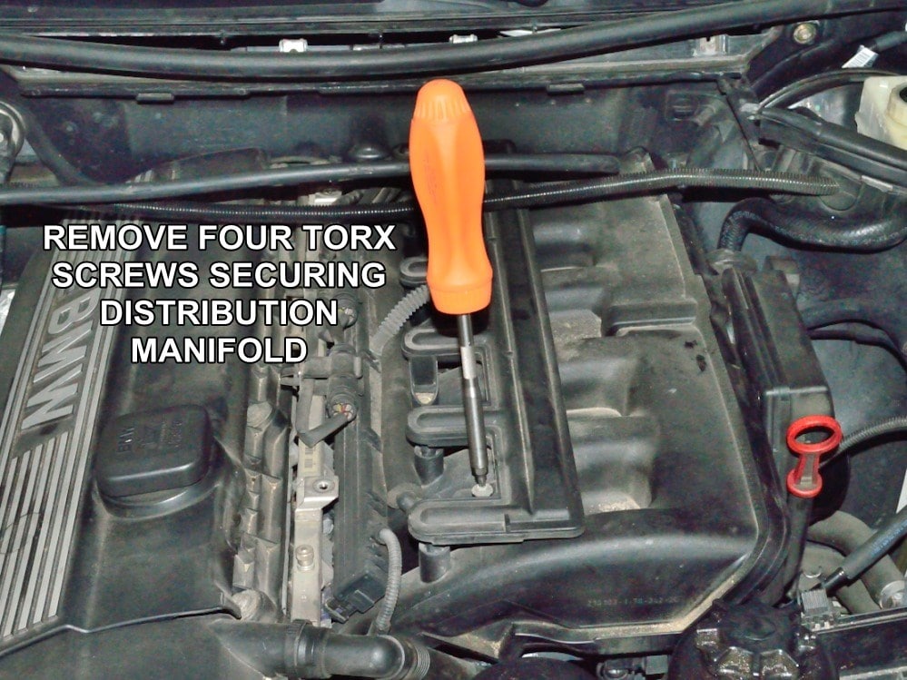
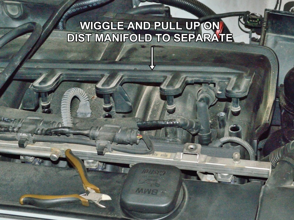
#14
Remove the torx screws securing the CCV air distribution manifold.
Make sure to use the proper torx bit as these are very tight and you don’t want to strip the heads of the screws.
#15
Lift off the distribution manifold by pulling up on one end to get it started.
You will probably need to wiggle and rock the manifold to get it loose. The o-rings tend stick themselves to the their bores with age.
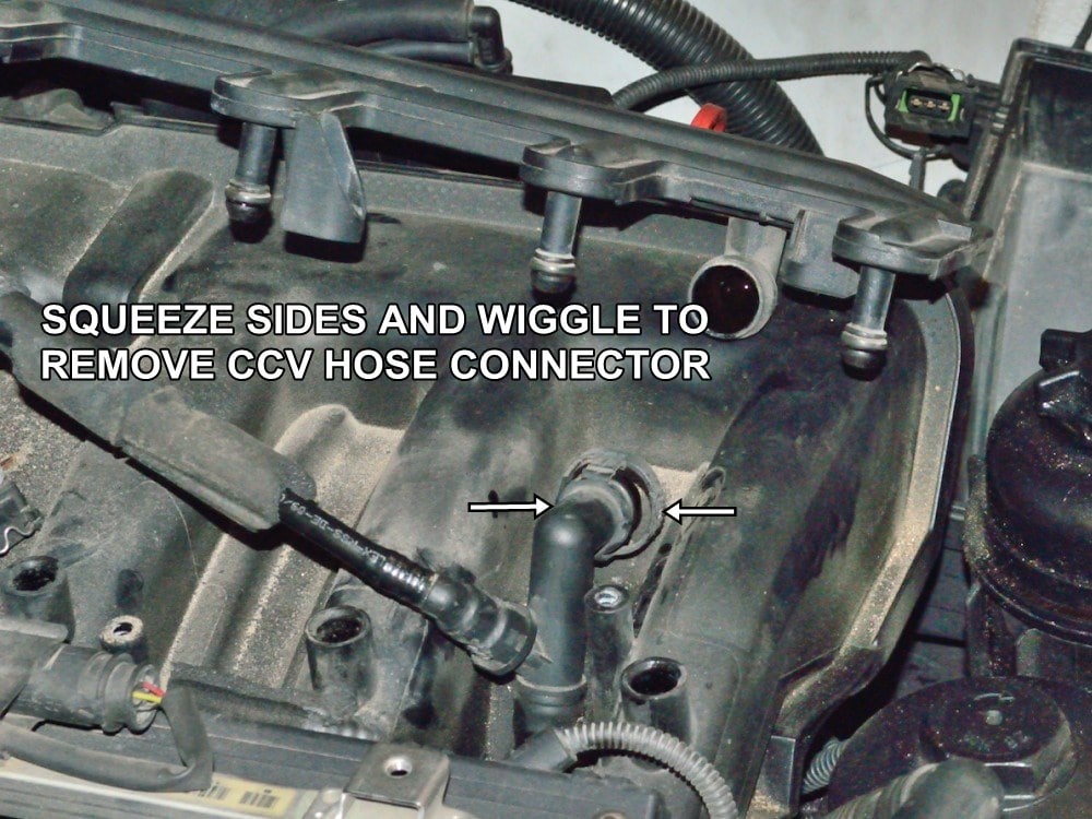
#16
Once the distribution manifold is free, squeeze the sides of the CCV hose connector and pull it free of the manifold.
Again, these are usually stuck pretty good and a lot of wiggling and rocking may be required to break it free.
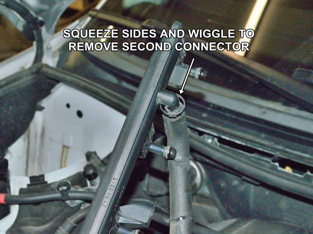
#17
Using the same procedure remove the secondary CCV hose connector from the distribution manifold.
Set the distribution manifold aside for now.
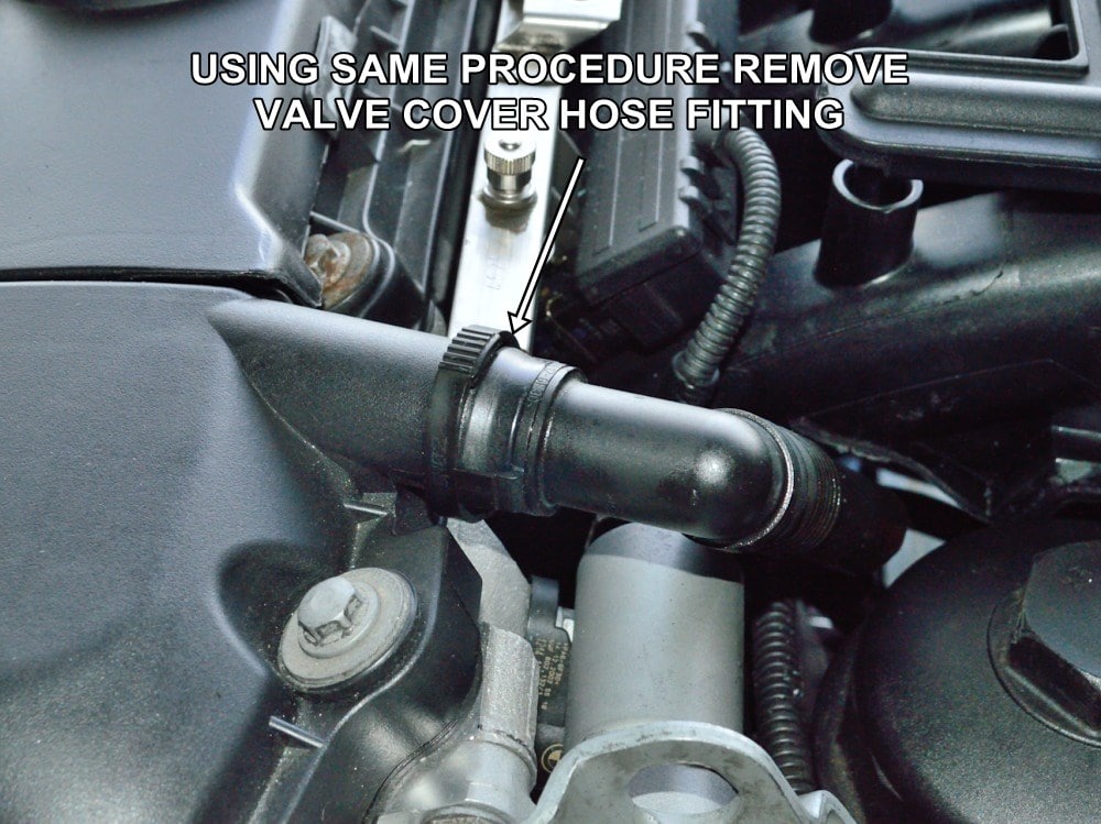
#18
Remove the valve cover hose from the valve cover.
Once the connector is free, grab the entire plastic hose firmly then pull and twist until it separates itself from the CCV body which is mounted under the intake manifold.
Discard the removed section of hose.
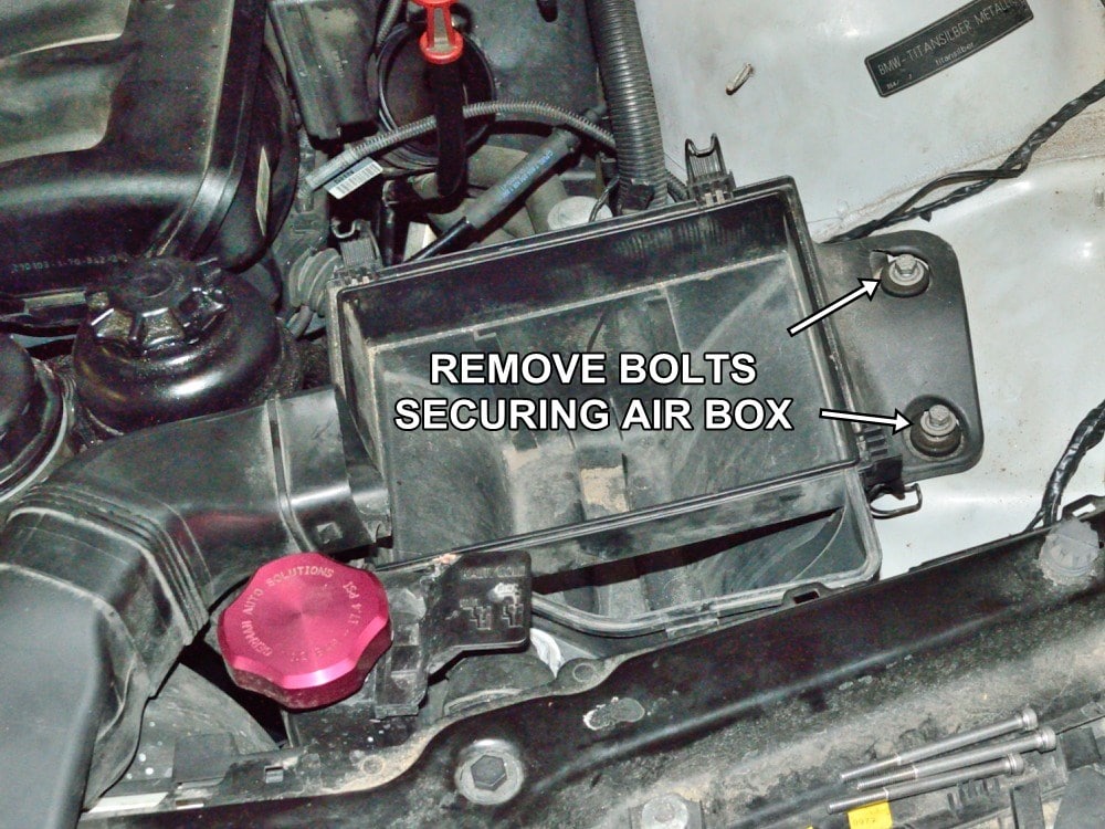
#19
Remove the bolts securing the air box.
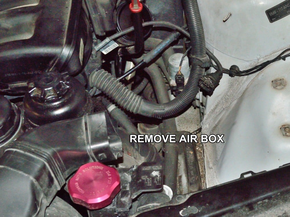
#20
Remove the air box.
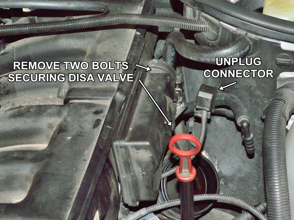
#21
Note: The next two steps cover removal of the DISA valve. Feedback from customers have shown that it isn’t always necessary to remove the DISA but it will give you more room to work. You can skip removal of the DISA if you feel you have enough room to work.
Unplug the connector from the DISA valve (adjuster unit in BMW terminology) then remove the two bolts securing the DISA valve to the intake manifold.
Again, use care to prevent stripping the heads of these bolts.
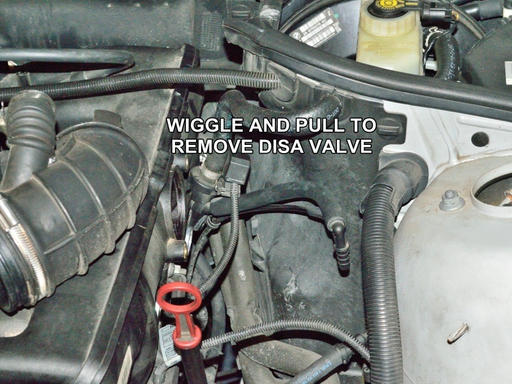
#22
Remove the DISA valve from the intake manifold by pulling straight outward while rocking the DISA valve housing.
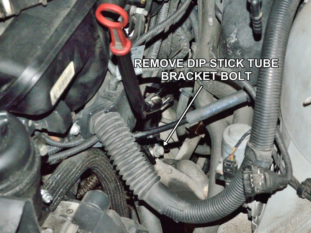
#23
Remove the bolt holding the dip stick tube bracket.
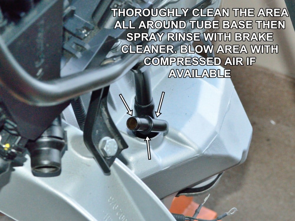
#24
This picture shows the dip stick tube mounted to an engine on an engine stand to better show the area that needs to be thoroughly cleaned. The next picture shows the same area on the vehicle with the dip stick removed.
CAUTION – Before removing the dip stick tube make every effort to clean all of the dirt and gunk around the base of the oil pan hole.
Most of what you miss cleaning off will fall down into the oil pan. Use aerosol brake cleaner and brushes to clean the area as thoroughly as possible before pulling out the dipstick tube. Blow the area with compressed air if available. Because of the limited ease of access to this area, this may be the hardest part of the CCV install.
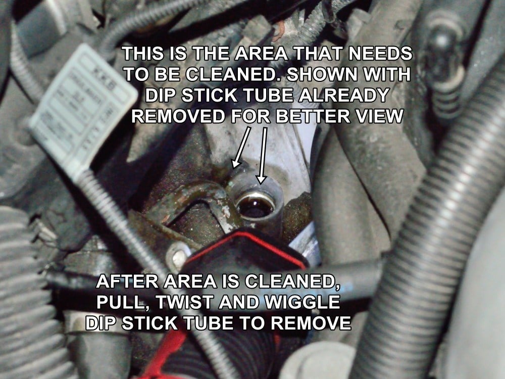
#25
This picture shows the dip stick tube already removed so that you can see the area that needs to be cleaned with the engine in mounted in the vehicle.
You can see from this picture how any dirt around the base of the dip stick tube can fall directly into the oil pan as the dip stick tube is removed.
Once clean, pull the original CCV drain back hose off of the dip stick tube nipple then pull out the dipstick tube.
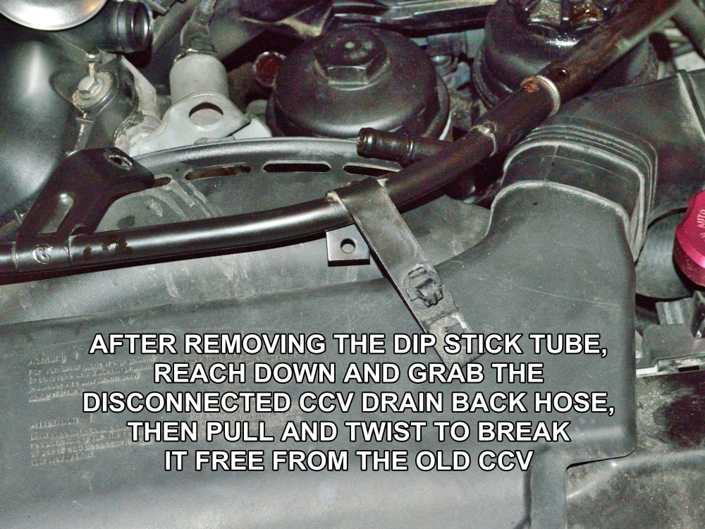
#26
Reach down and grab a hold of the old CCV drain back hose that you just disconnected from the dip stick tube and pull or break it free of the stock CCV unit and throw it away.
If you plan on re-using the original dip stick tube, make sure that the area between the inner and outer tube is thoroughly clean. Spray brake cleaner down the drain back nipple and it should easily pass all the way through and out the bottom of the tube.
For the reasons stated at the beginning of these instructions, it is highly recommended that you replace your original dip stick tube withe the “Cold Climate” single tube version.
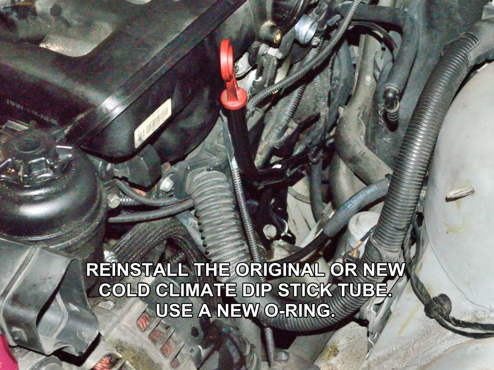
#27
Reinstall the new or “cleaned and verified to not be plugged” dip stick tube using the new o-ring supplied with the kit.
Wet the new o-ring with clean engine oil before reinstalling the dip stick tube.
Reinstall the dip stick tube bracket bolt and tighten.
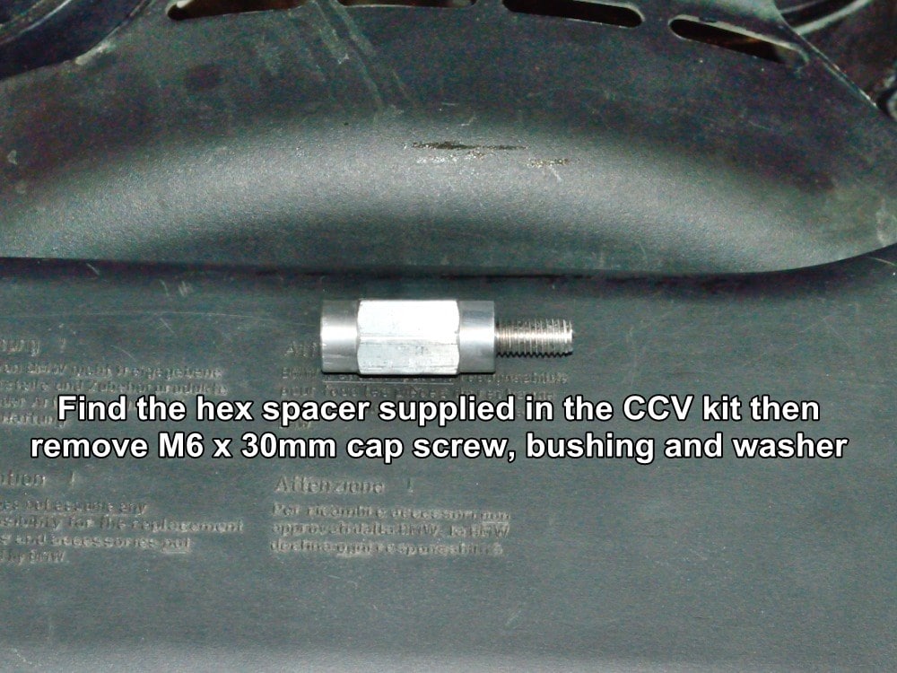
#28
Find the hex spacer with 8mm stud from the kit.
Remove the M6 x 30mm cap screw, flat washer and bushing from the hex spacer and set them aside for now.
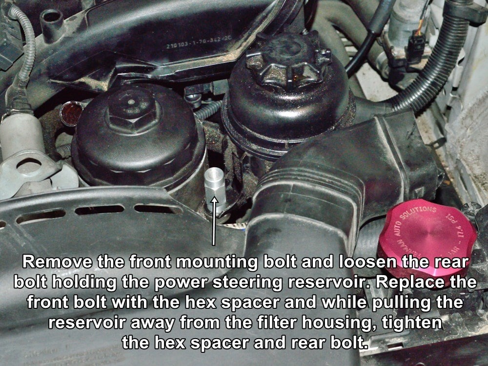
#29
Remove the front bolt holding the power steering reservoir and replace it with the spacer and stud as shown.
Screw the spacer in just until it contacts the reservoir mounting bracket then loosen the rear mounting bolt a little.
While pulling on the reservoir in the direction away from the oil filter housing, snug, then tighten the rear mounting screw and hex spacer. The object is to use any slop in the reservoir mounting bracket holes to gain a little more room for the CCV.
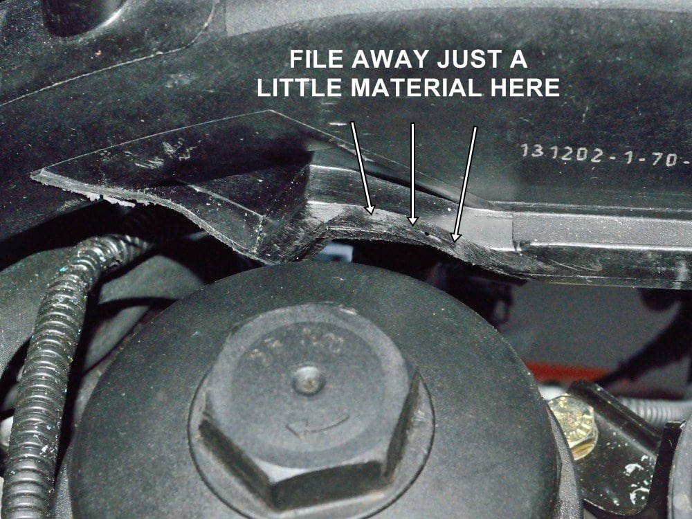
#30
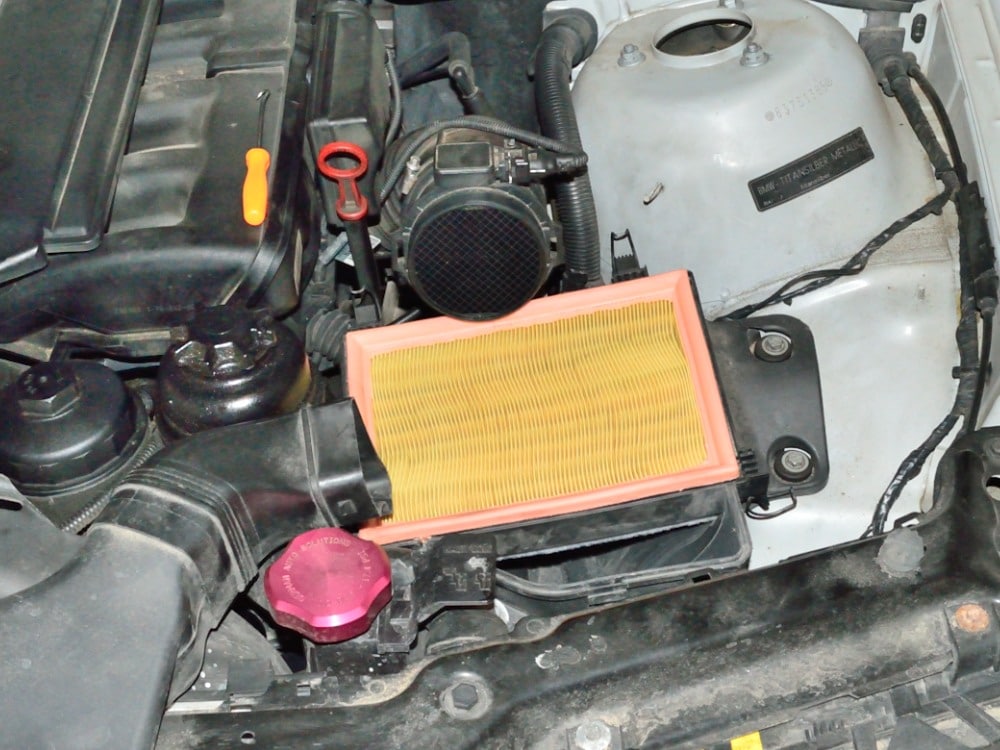
Before removing the oil filter cap you will need to file a little material off of the lip on the intake manifold to clear the CCV mounting base. This may not be required on 2.5L liter engines.
If you look straight down at the oil filter cap from directly above the cap, the lip on the manifold needs to match the outer rim of the filter cap.
In other words, if you pulled exactly straight up on the filter cap, it should be able to pass by the lip of the intake manifold without touching it.
You will test fit the mounting base shortly.
#31
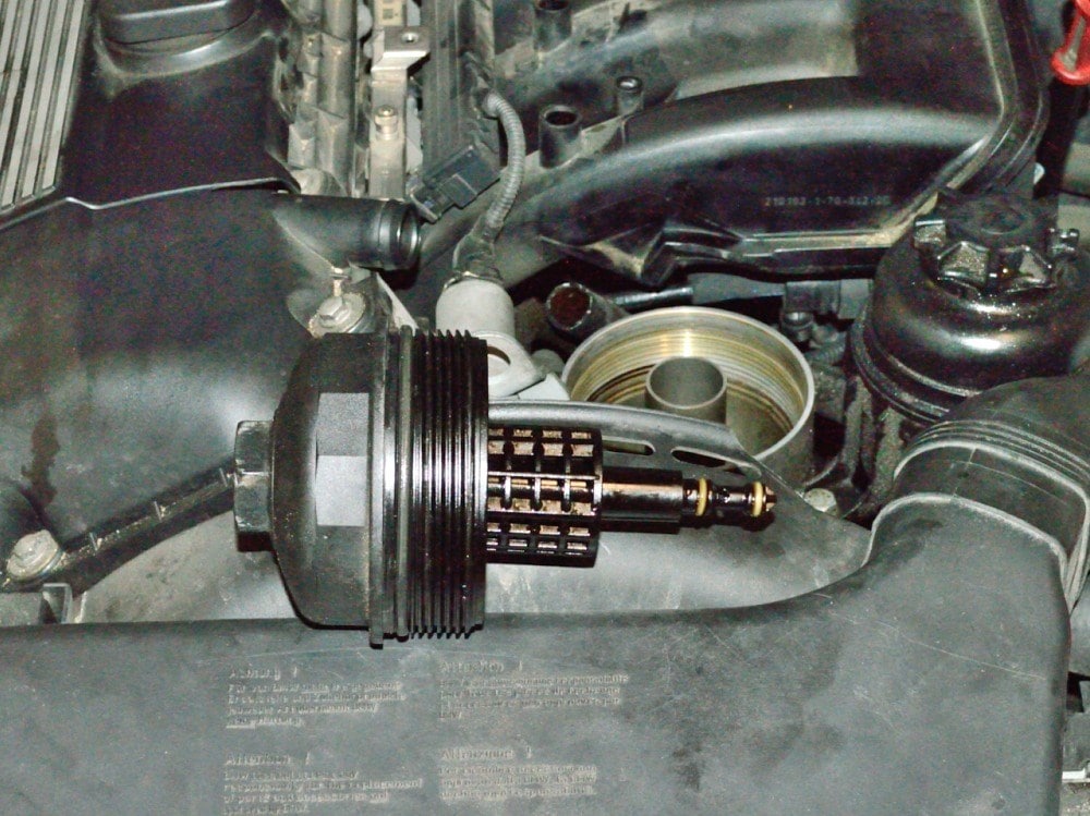
Remove the oil filter cap and oil filter using a 36mm socket.
Dispose of the used oil filter.
#32
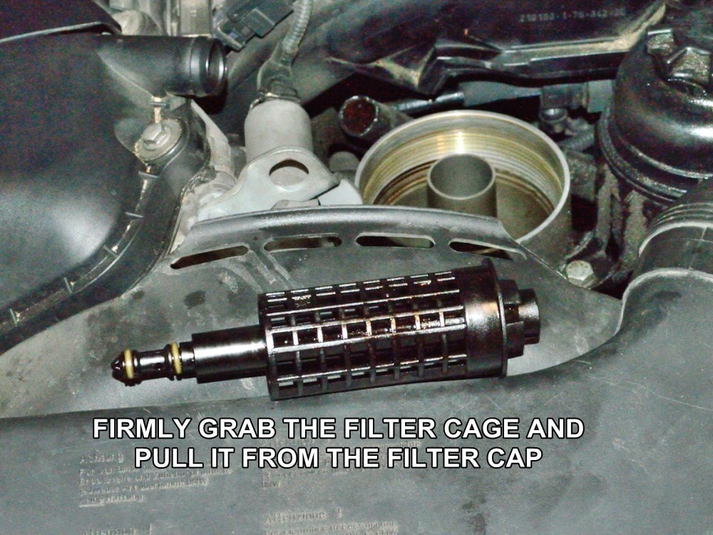
Firmly grasp the filter cage with one hand and the filter cap with the other then twist and pull to separate the filter cage from the cap.
Nothing will break here, the filter cage just snaps in and out the filter cap.
The picture shows the cage after being separated from the cap.
From here forward the pictures shown will be of an engine mounted on an engine stand. This allows for better lighting, more detail and easier access to confined areas of the engine for picture taking.
#33
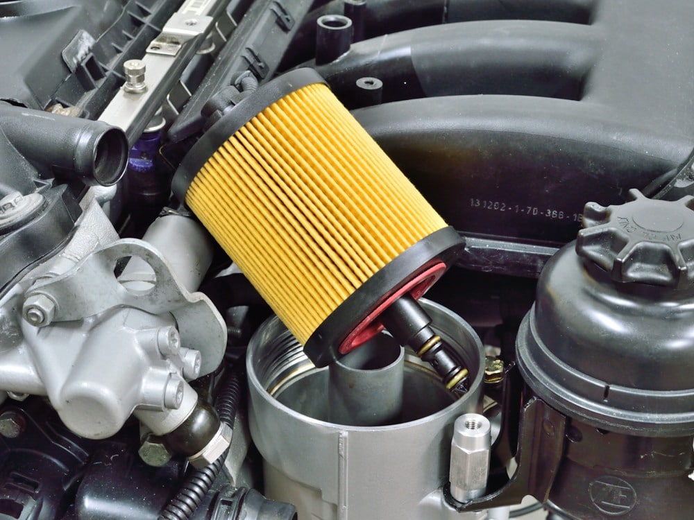
Install a new oil filter element onto the filter cage.
Set the filter and cage aside and temporarily.
#34
Next we will test fit the CCV mounting base assembly before we attach and install the drain hose.
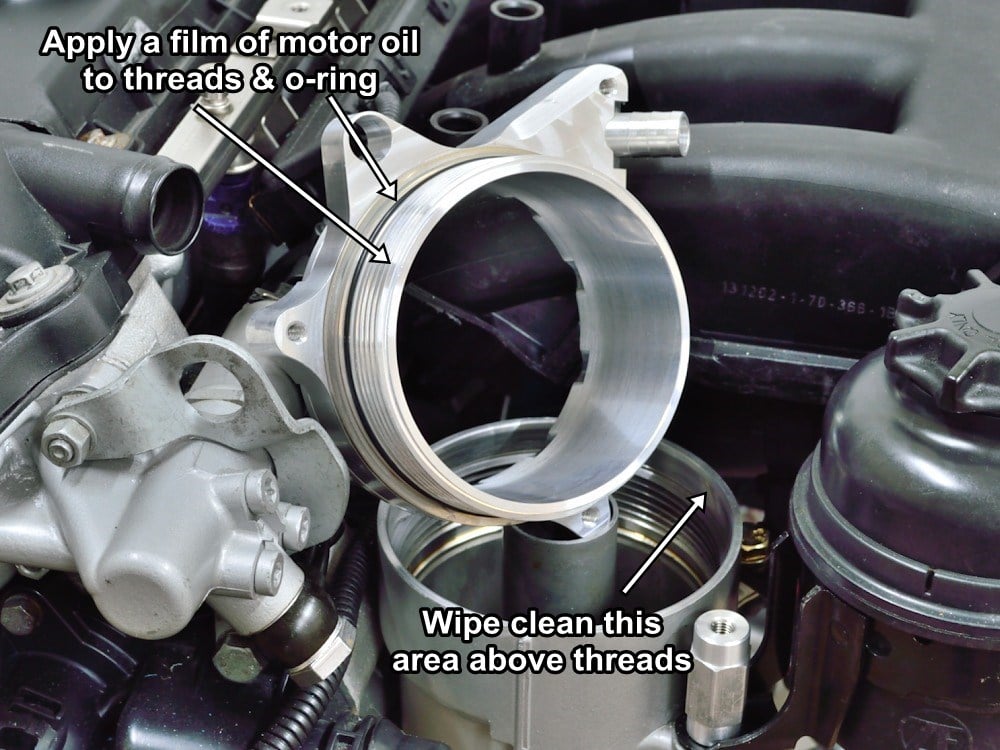
Wipe the inside of the oil filter housing above the threaded area clean with a clean lint free cloth or shop towel.
Prepare the G.A.S. CCV mounting base for test fitting by coating the threads and bottom o-ring (the one next to the threads) with clean motor oil.
#35
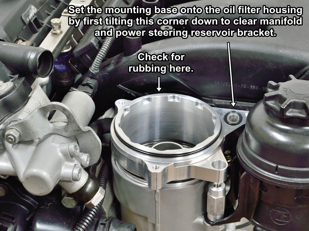
Wipe a little clean motor oil around the just cleaned surface on the inside wall of the filter housing then set the mounting base assembly in place as shown.
You will need to tilt the right front corner of the base down and maneuver the base into place. It’s a tight fit.
Make sure that the CCV mounting base is sitting square and flat on top of the oil filter housing and that it is not rubbing against the intake manifold lip.
If the base won’t sit flat without rubbing DO NOT attempt to screw it in. You will need to remove the mounting base, put the oil filter cap back on, then file off a little more material from the intake manifold lip where it’s rubbing.
#36
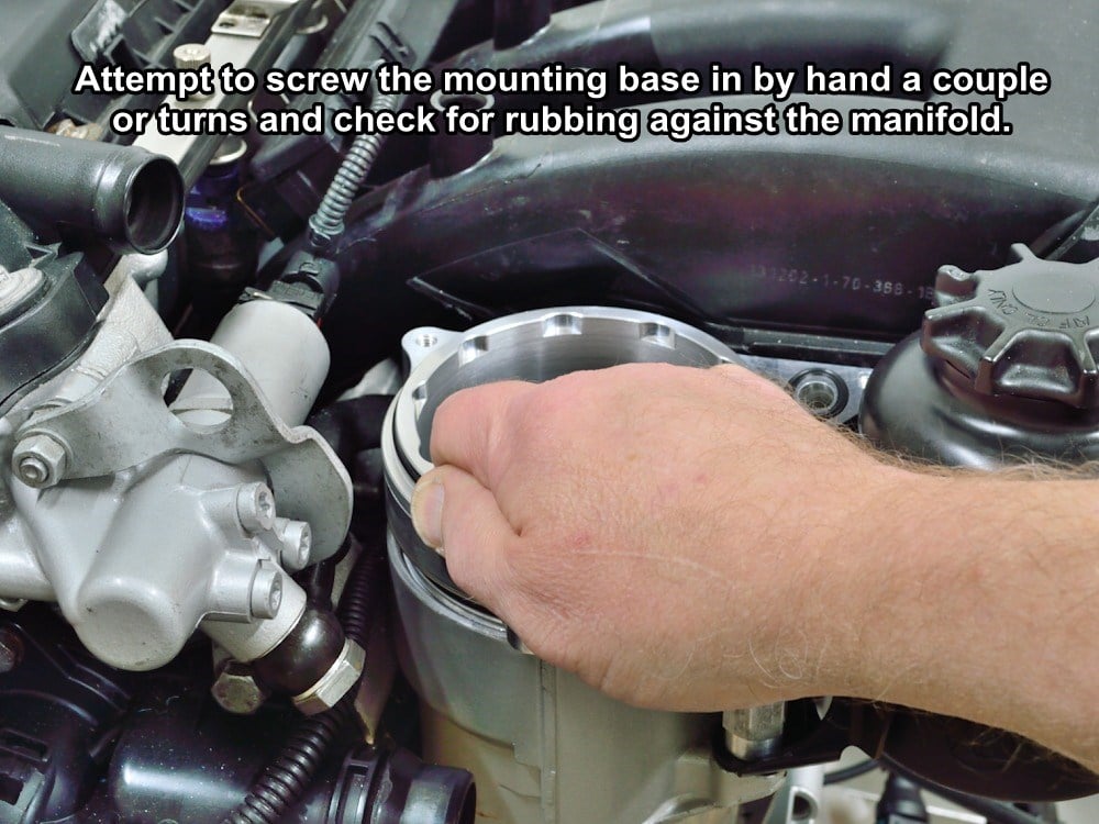
Once you get the mounting base to sit flat without rubbing, grasp the top rim of the base and make sure that you successfully screw the mounting base into the filter housing a couple of turns without any binding against the intake manifold.
The outer base will want to turn with inner section as you screw it in so you will need to hold the outer section to keep it from turning as you go.
If the mounting base rubs or binds against the intake manifold as you screw it in you will need to remove the mounting base, put the oil filter cap back on, then file off a little more material from the intake manifold lip where it’s rubbing.
If everything fits well remove the mounting base and temporally set the old filter cap back onto the filter housing for the next couple of steps..
Find the 19.75 inch rubber hose that is supplied with the kit.
In the next two steps we will be installing hose clamps onto the hose. The kit comes with three hose clamps. One “spring type” and two “crimp type” clamps. If you want the ability to remove the CCV mounting base later without having to cut a hose clamp then use a “spring” clamp on one end of the hose and a “crimp” clamp on the other. If you don’t care, use a “crimp” clamp on both ends.
Using “crimp” clamps on both ends also makes the mounting base a little easier to install because you do not have to maneuver the larger spring clamp past the power steering reservoir.
#37
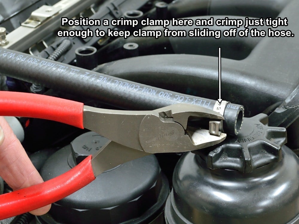
Slide a “crimp” style hose clamp over one end of the rubber hose to the position shown.
Using a large pair of diagonal cutters, crimp the clamp just enough to keep the clamp from wanting to slip off of the hose when the hose is tilted downward.
You don’t want the clamp so tight that the hose cannot easily slip over the dip stick tube nipple.
#38
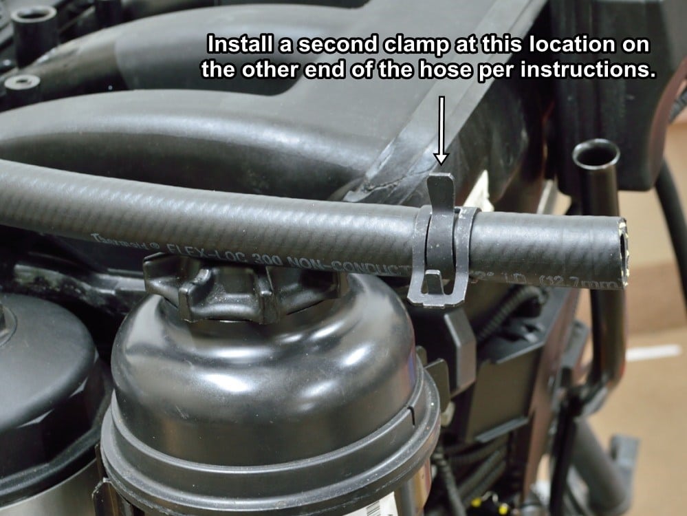
If you are using a “spring” style clamp on the mounting base end of the hose, squeeze it with a pair channel lock pliers and slide it onto the other end of the hose to location shown.
If you are using a “crimp” style clamp use the same procedure from the previous step to position the clamp at the location shown.
#39
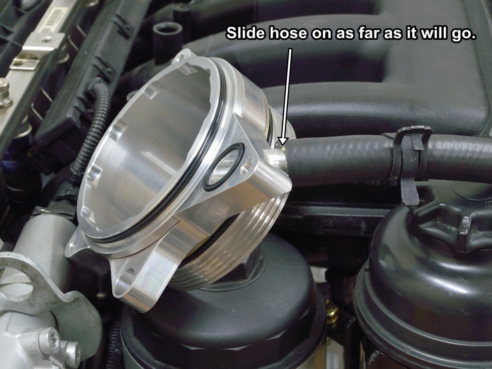
Slide the end of the hose that you just installed the clamp on, over the nipple on the mounting base.
Slide the hose on as far as it will go.
#40
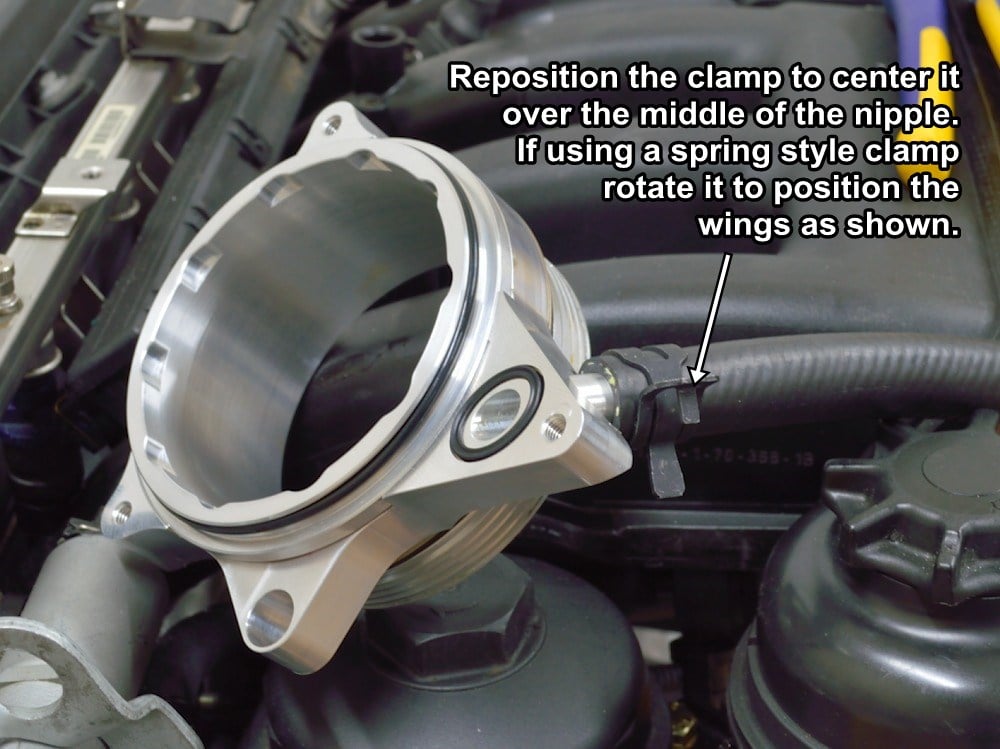
Reposition the hose clamp to the location shown which is approximately in the middle of the nipple.
If using a “spring” clamp do not position the clamp too close to the mounting base. It will make the base difficult to install. You also want the clamp to be rotated to the position shown in the picture. When looking at the end of the hose you want the wings of the clamp at about the four o’clock position relative to the top of the mounting base.
If using a “crimp” style clamp, position the crimping nub at about the three o’clock position.
#41
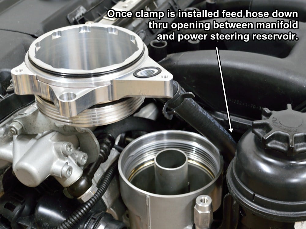
Once the clamp is in place remove the old filter cap from the filter housing then slide the hose down between the filter housing and power steering reservoir as shown.
See the next step for the proper routing of the hose below the manifold.
#42
Once the clamp is in place, remove the old filter cap from the filter housing, then slide the hose down between the filter housing and power steering reservoir as shown.
See the next step for the proper routing of the hose below the manifold.
#43
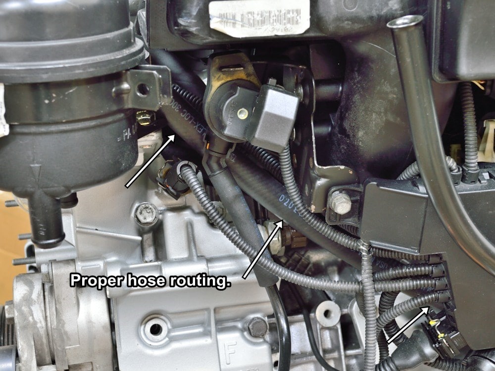
Here is a wider angle view of the hose routing.
#44
With the hose properly routed, tilt and maneuver the CCV mounting base into position as you did before during the test fitting.
#45
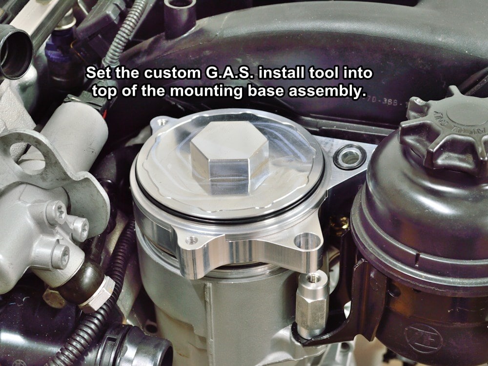
Set the custom install tool into the top of the G.A.S. CCV mounting base assembly.
#46
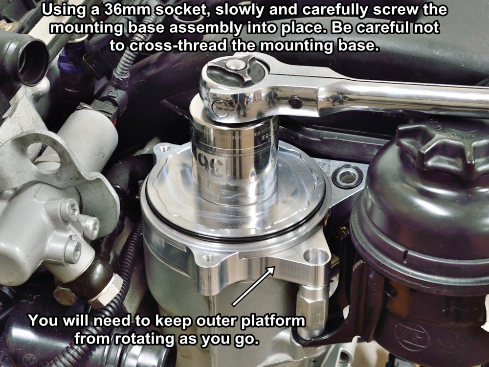
First by hand, then using a 36mm socket and ratchet, slowly screw the mounting base into place. Use caution for the first few turns to make sure that you do not cross thread the base.
You will need to hold the outer platform of the mounting base in the orientation shown and keep it from rotating while screwing the assembly into place.
Screw the mounting base in until it is fully seated against the filter housing then tighten just until snug with the 36mm socket and ratchet. The outer section of the mounting base should still be able to swivel back and forth a little, if it won’t, back off slightly on the base tightness.
Leave the custom tool in place for the next few steps to keep any dirt from falling into the oil filter housing.
#47
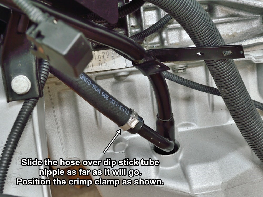
Now that the base is installed the hose will reach the dip stick tube nipple.
Slide the hose all the way over the nipple as shown.
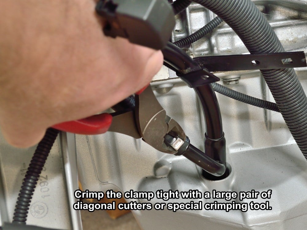
#48
Using a dedicated crimping tool, or large pair of diagonal cutters, crimp the clamp tightly over the hose.
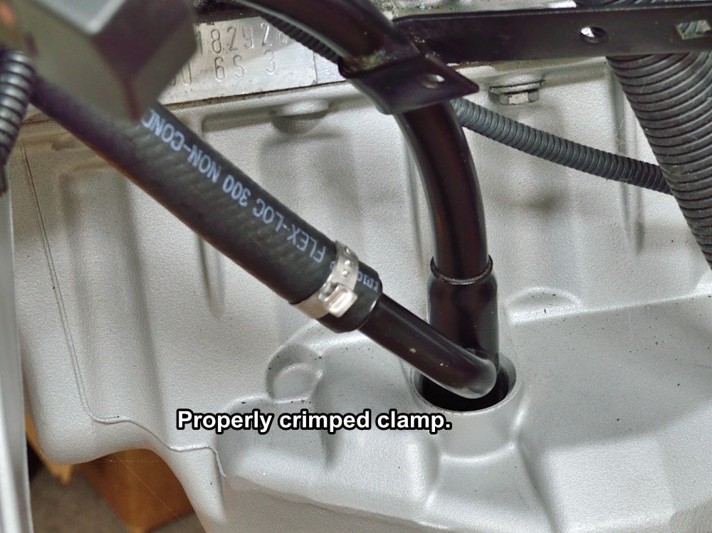
#49
This is what the properly crimped clamp should look like.
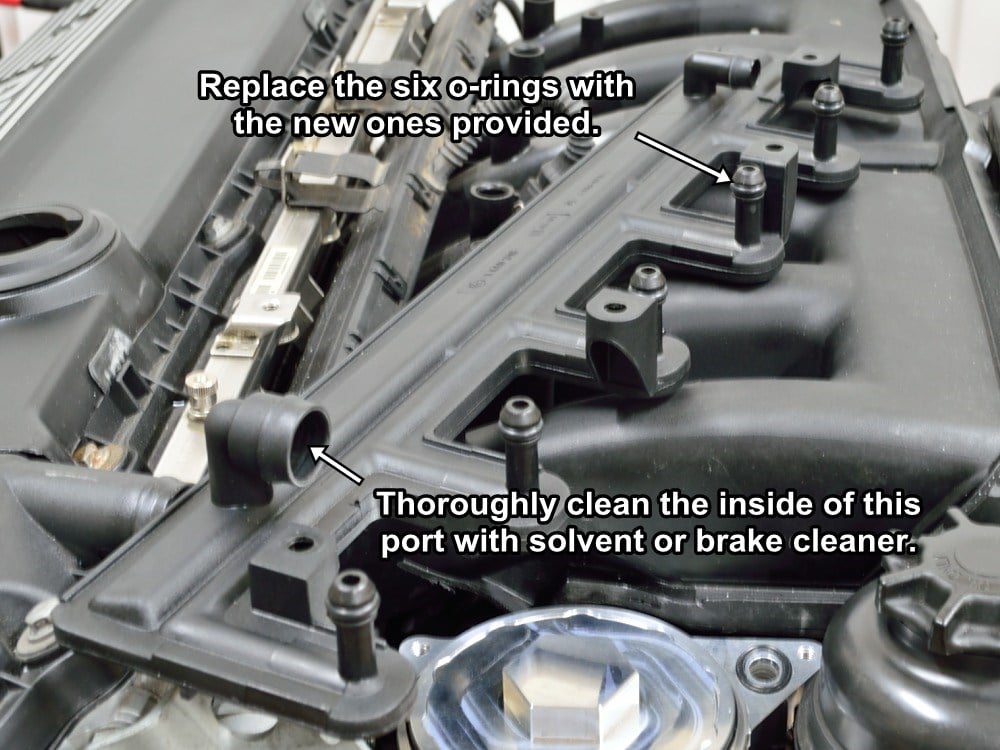
#50
Find the distribution manifold and replace the six o-rings with the new ones supplied with the kit.
Thoroughly clean the inside of the larger of the two connecting ports. The G.A.S. CCV manifold will seal with an o-ring into the inside of the port so it needs to be free of any crud or carbon build up.
Wet the six new o-rings with clean motor oil.
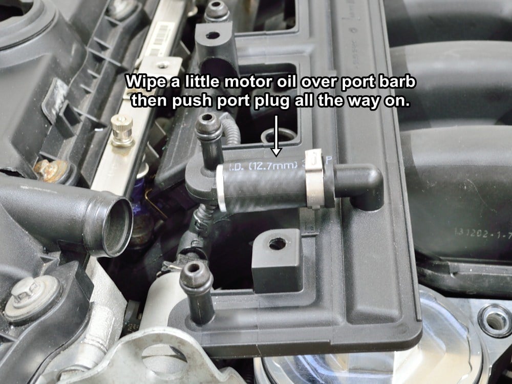
#51
Wipe a little clean motor oil over the barb on the smaller of the two main ports. Push the supplied port plug over the port as shown.
Make sure you push the plug on all the way on until it stops. The end of the hose should go past the ridge on the port.
Use your remaining hose clamp here.
#52
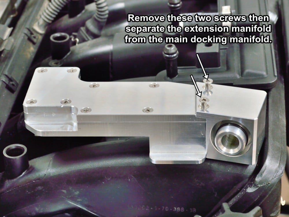
Find the G.A.S. CCV docking manifold.
Remove the two screws holding the manifold extension, then remove the extension and set it aside for now.
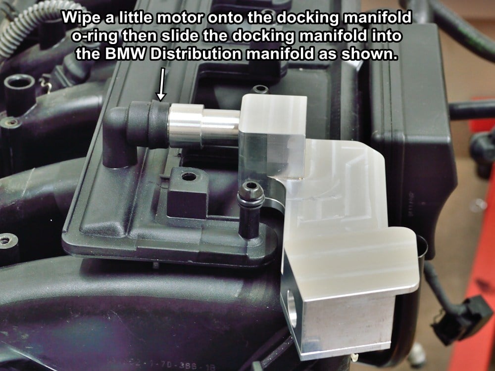
#53
Wet the o-ring and the inside of the distribution manifold port with clean motor oil.
Slide the G.A.S. docking manifold into the BMW distribution manifold as shown.
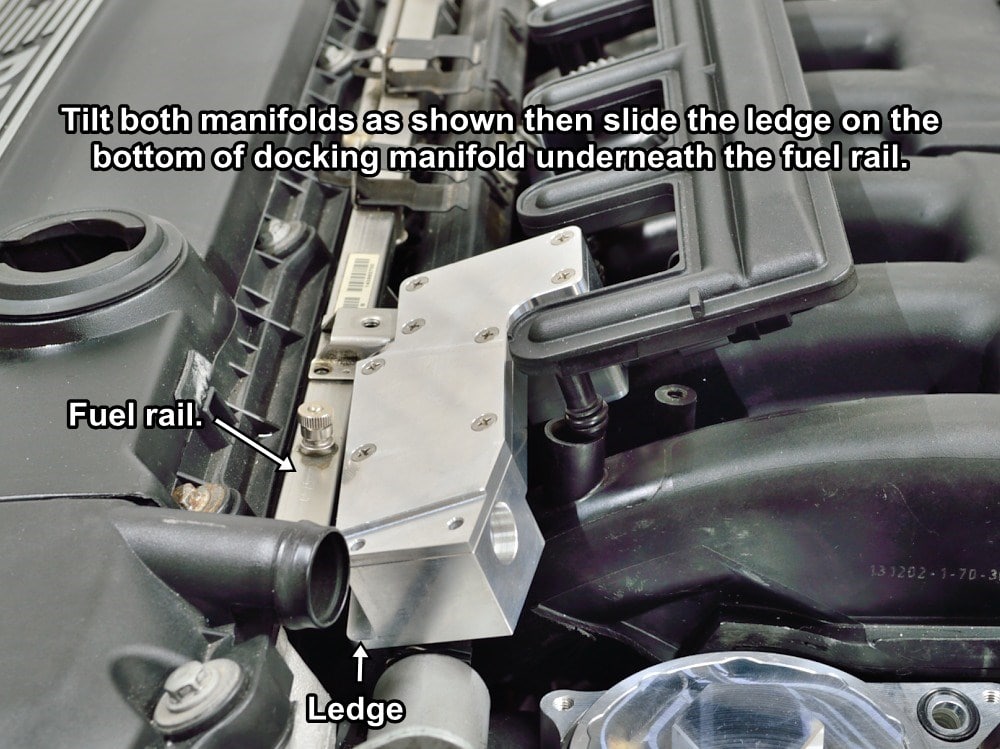
#54
Tilt the manifolds as shown then slide the lip on the G.A.S. docking manifold underneath the fuel rail as shown.
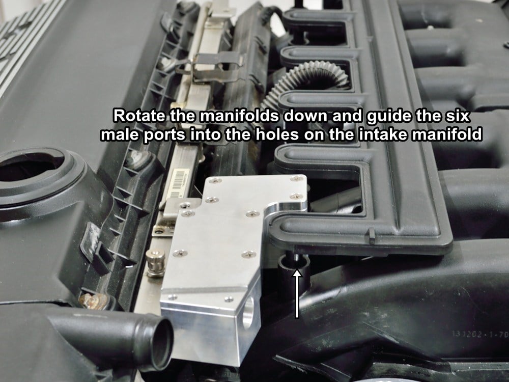
#55
Rotate the manifolds downward then seat the BMW distribution manifold down into the six holes in the intake manifold.
Firmly seat the BMW distribution manifold into place then reinstall the distribution manifold mounting screws.
#56
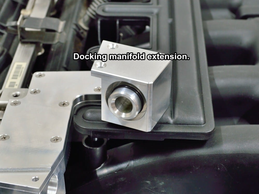
Find the G.A.S. CCV docking manifold extension with short fitting shown.
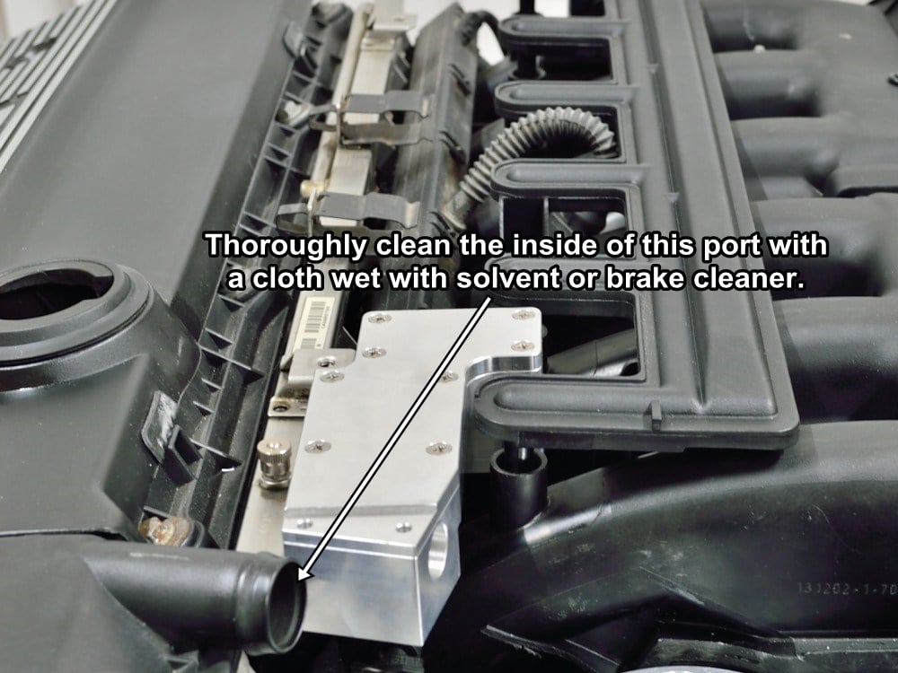
#57
Thoroughly clean the inside of the valve cover manifold port with solvent or brake cleaner.
An o-ring seals to the inside of the valve cover port so it needs to be completely clean and free of crud and carbon deposits.
Once cleaned, apply a film of clean motor oil to the inside of the valve cover port.
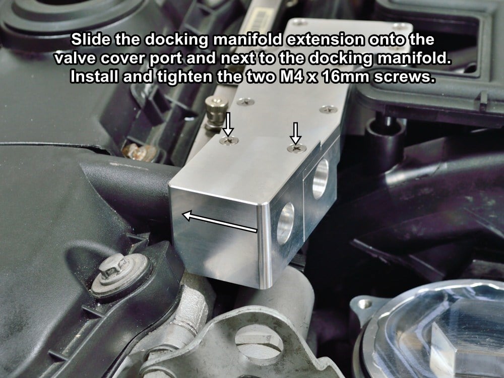
#58
Slide the docking manifold extension over the valve cover port and next to the main manifold as shown.
Push the manifold all the way in until it sits flush with the front face of the main docking manifold.
Install the two M4 x 16mm flat head screws to secure the two manifolds together.
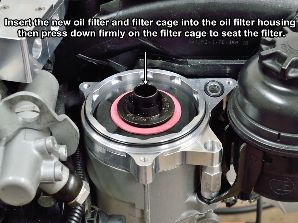
#59
Remove the custom install tool from the mounting base then insert the oil filter and filter cage into the oil filter housing as shown.
Press the filter cage down until it’s fully seated.
#60
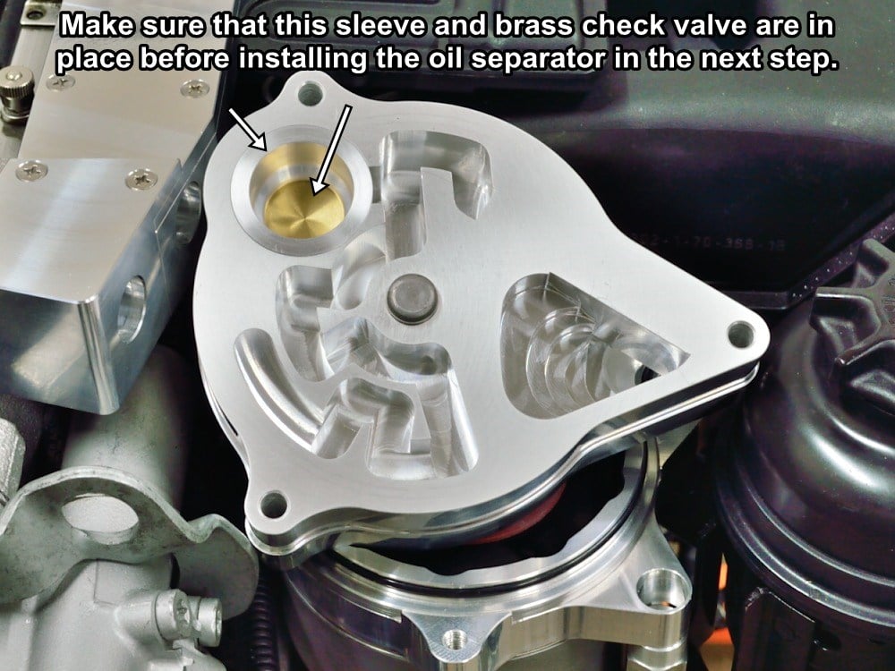
Find the G.A.S. CCV oil separator.
Make sure that the removable sleeve and brass check valve are in place as shown. The sleeve is held in place by the fiction of an o-ring around its circumference. The o-ring does not seal anything. It is there only to prevent the sleeve and check valve from falling out during servicing.
The G.A.S. CCV MUST NOT EVER be operated without these in place!
#61
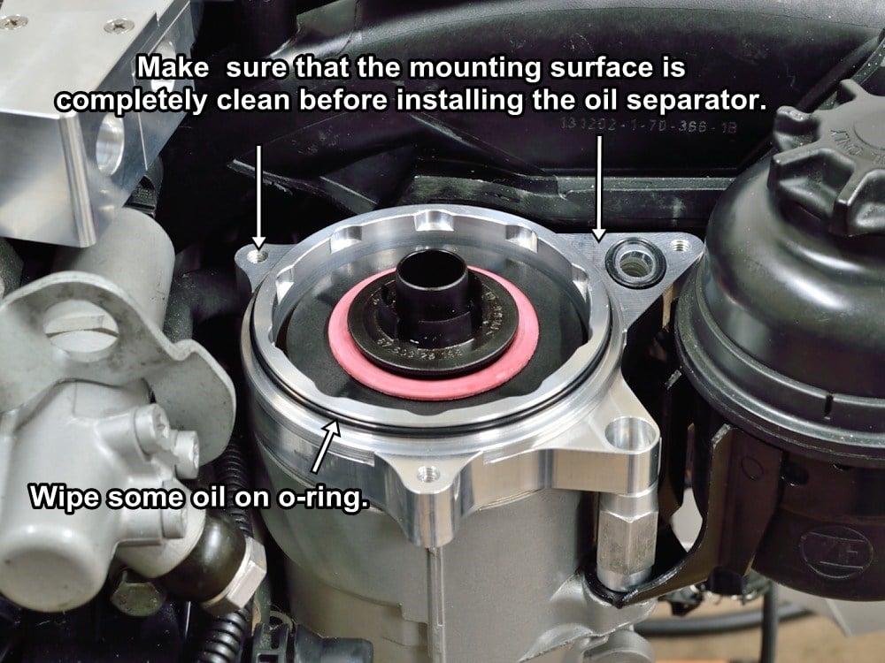
Make sure that the all of the surfaces on the CCV mounting base and both o-rings are completely clean. Wipe with a lint free cloth or your hand.
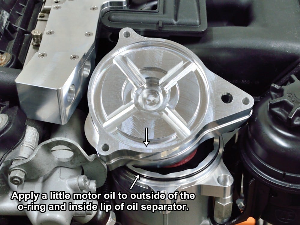
The mounting base o-ring comes preluded with a clear PTFE grease but it doesn’t hurt to lube the outside of the mounting base o-ring (not the small oval one) with clean engine oil before assembly.
#62
Use your finger to wipe a little oil on the inner lip of the oil separator before assembly.
#63
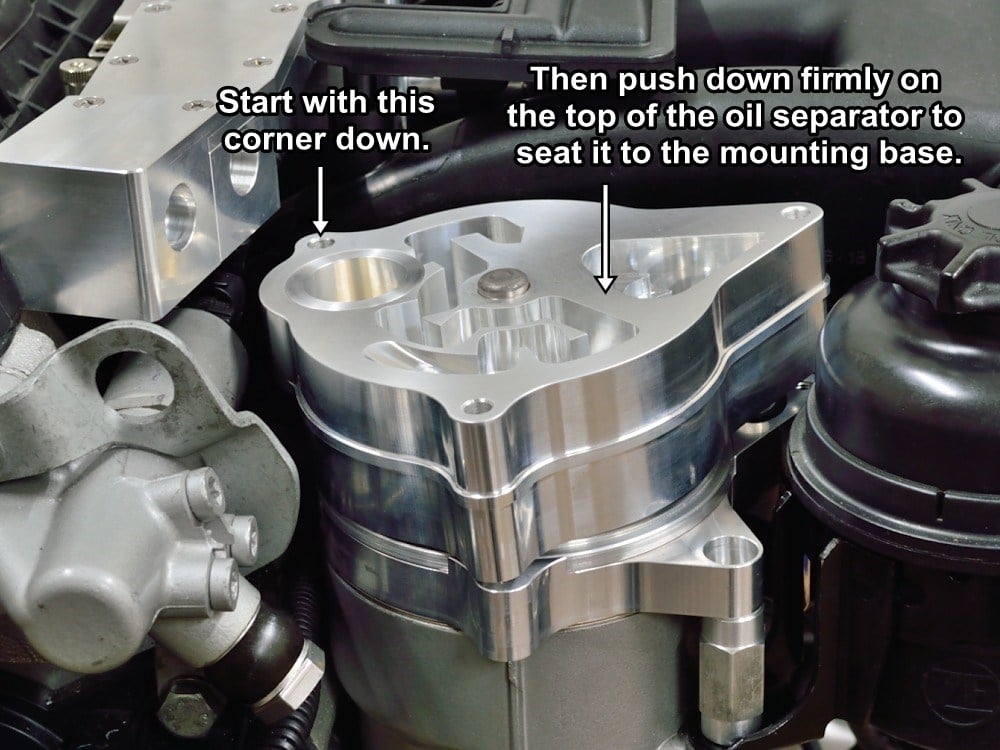
Set the oil separator onto the CCV mounting base as shown.
It seems to work best to start with the left rear corner of the oil separator sitting lower and over the edge of the mounting base o-ring as shown.
Press down squarely and firmly on the oil separator until the raised side of the separator pops over the o-ring and is fully seated against the mounting base.
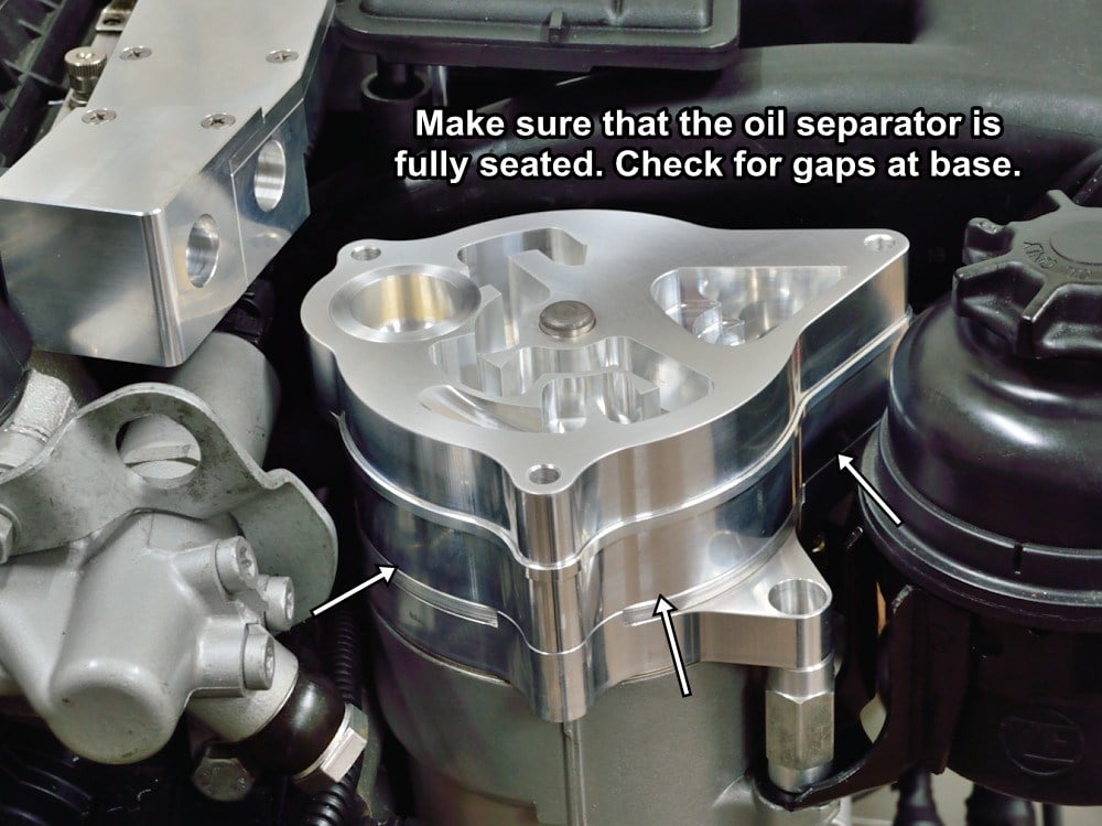
#64
Make sure that the oil separator is fully seated all the way around as shown before trying to install the vacuum regulator in the next step.
#65
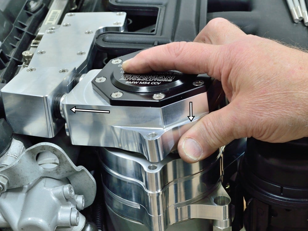
Find the G.A.S. CCV Vacuum Regulator.
Slip the two nipples into the docking manifold assembly, then carefully seat the vacuum regulator down onto the oil separator by pushing it toward the manifold and down until it seats onto the center dowel pin.
The center steel dowel pin will locate the vacuum separator in position for installing the three M6 x 80mm socket head cap screws.
If the vacuum regulator won’t sit down over the dowel pin and flat against the top of the oil separator, double check to make sure that the oil separator is fully seated onto the mounting base.
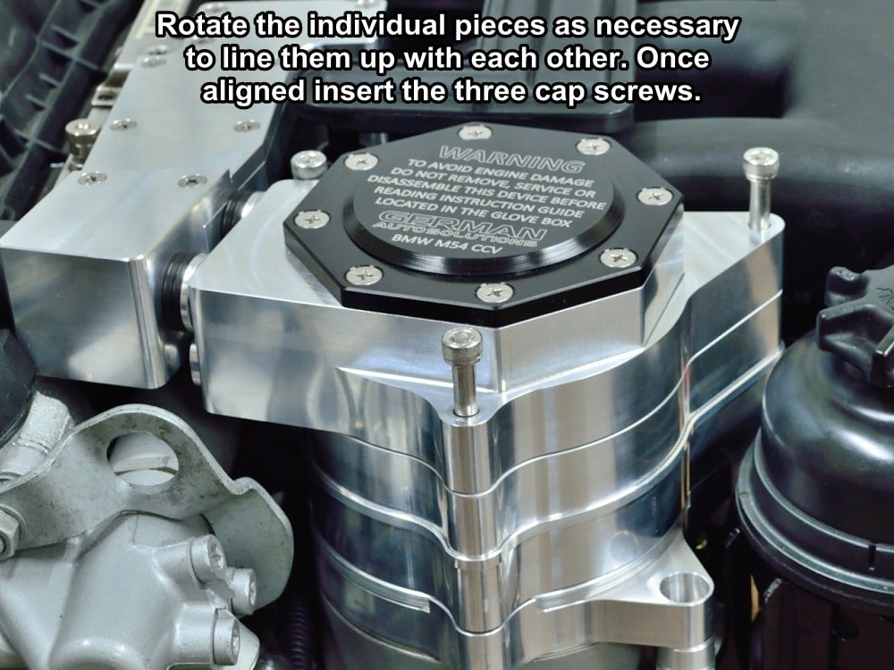
#66
Rotate the vacuum regulator, oil separator and mounting base as necessary to bring all three pieces into alignment.
Set the three 6mm x 80mm cap screws in place as shown.
Start the screws into the threads but DO NOT tighten yet.
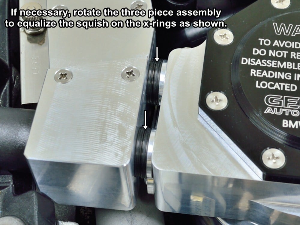
#67
Check that the double stacked x-rings on the vacuum regulator nipples are compressed fairly equally.
If the x-rings do not seem to be compressed equally, rotate the assembly as necessary to correct the problem.
#68
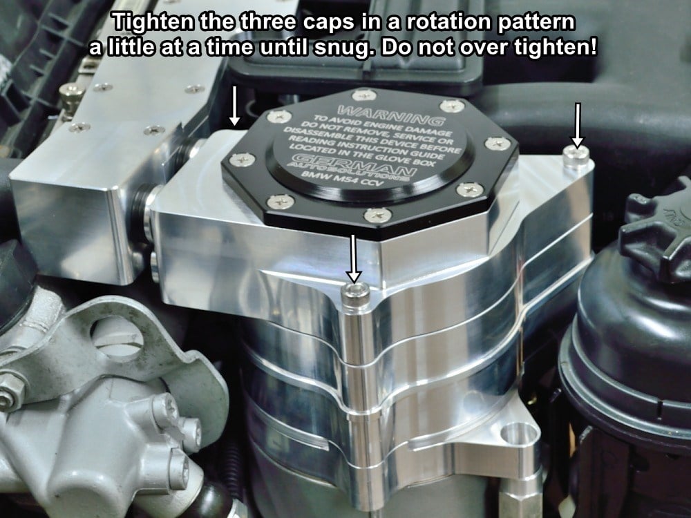
Once everything is aligned, tighten the three screws until they just touch the top of the vacuum regulator. Now snug them up a little at a time in a rotational pattern.
There is no need to over tighten these. The assembly expands as it heats up which increases the load on the screws. A torque of 5 ft.lb. (7 Nm ) is enough.
Unfortunately most foot-pound torque wrenches don’t go down to 5 ft.lbs.
#69
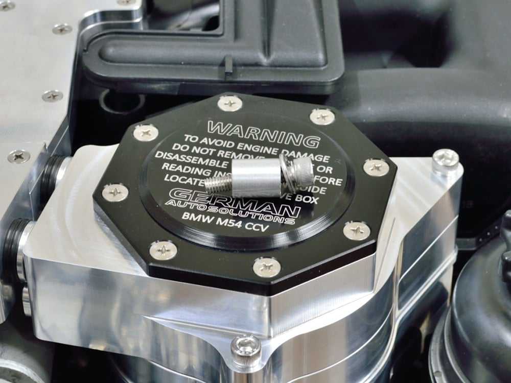
Find the M6 x 30mm cap screw, washer, and bushing that were previously removed from the the hex spacer.
I need to say a few words here about the CCV alignment before you perform the next two steps. The two parameters that effect the rotational alignment of the CCV are the position of the port on the valve cover and the position or the stock oil filter housing on the engine block. There has only been one version of oil filter housing that I know of and it is dowel located when installed at the factory. If the filter housing hasn’t been removed or replaced and then reassembled with missing dowels the position should not change. The same applies to the valve cover.
That being said, we have seen at least one instance of the G.A.S. CCV not being able to align with the mounting base in the next two steps. If you cannot install the 6mm screw in the next steps because of a rotational alignment issue causing the bushing to partially cover the mounting hole, please contact us and let us know. We need to know if there are some dimensional variances of the BMW oil filter housing so that we can try to find a solution to the problem.
It is okay to delete the bushing if that is want is required in order to get the 6mm screw to thread in. If you delete the bushing DO NOT fully tighten the 6mm screw, just snug it up a little. The screw is meant to seat against the bushing, and if it is missing, tightening the screw will slightly bend the mounting base.
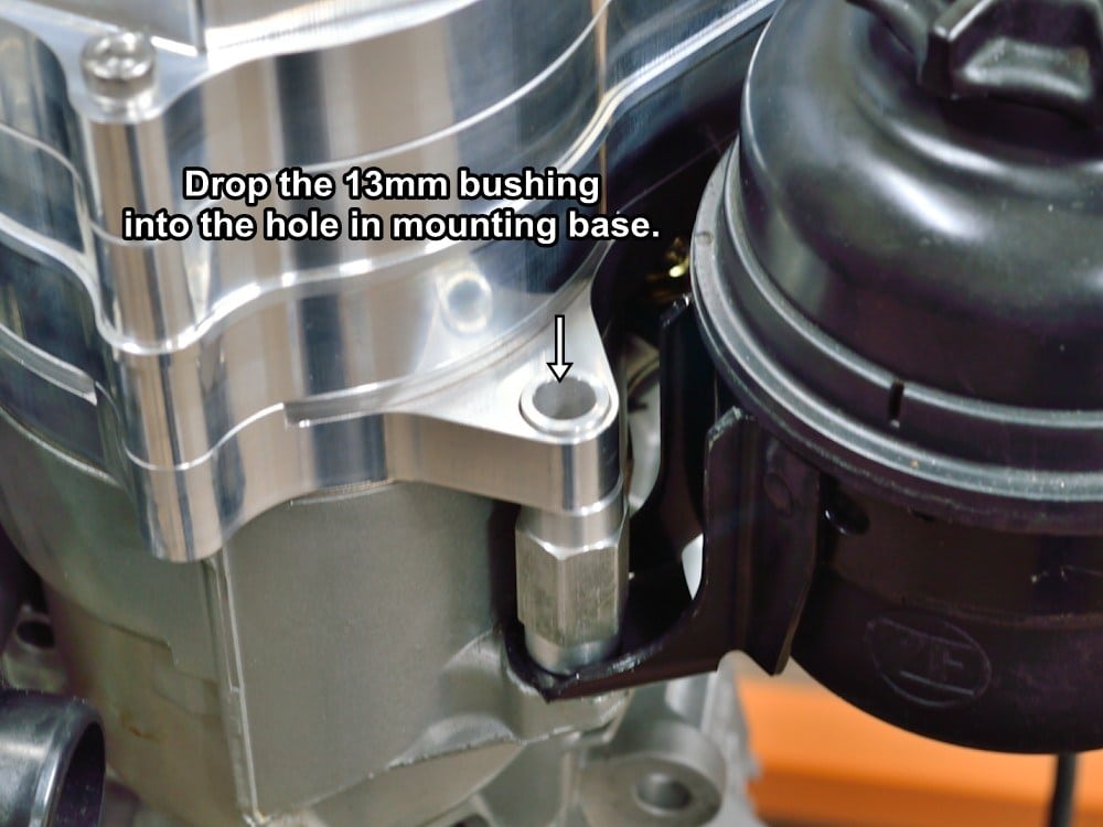
#70
Drop the spacer into the hole on the mounting base as shown.
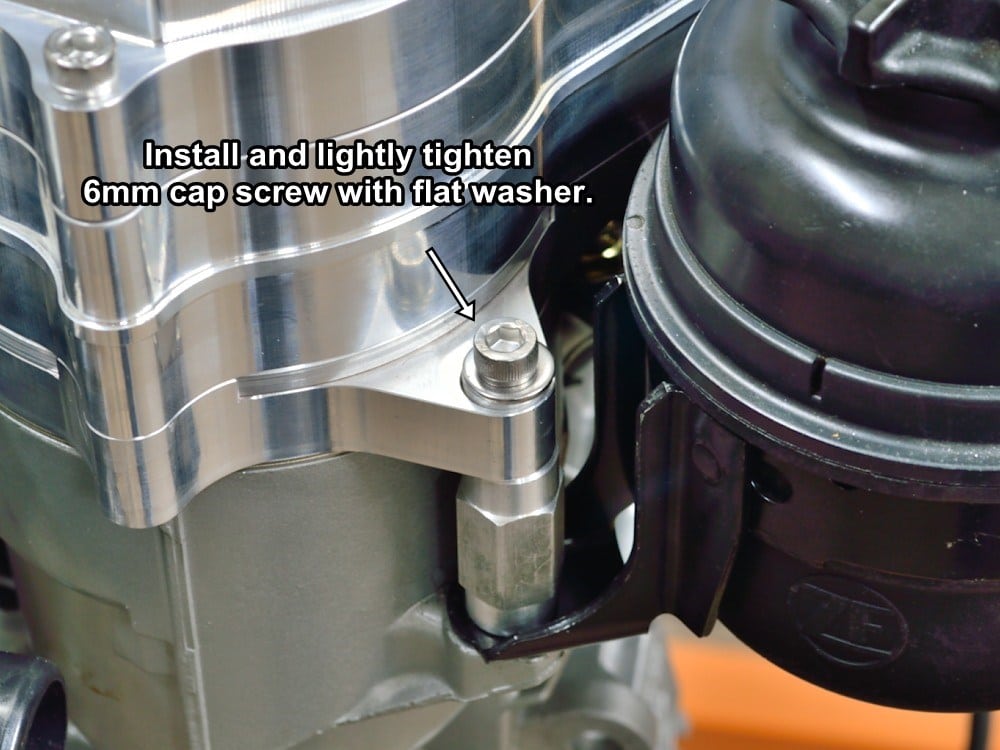
#71
Drop the M6 x 30mm cap screw into the bushing then tighten until snug. This permanently locks the alignment of the mounting base so that everything stays lined up for easy reassembly when servicing the CCV.
If you cannot start the bolt because the bushing is partially covering the hole you may need to loosen the three M6 x 80mm cap screws and rotate the whole assembly a little until the threaded hole is exposed enough to start the screw.
#72
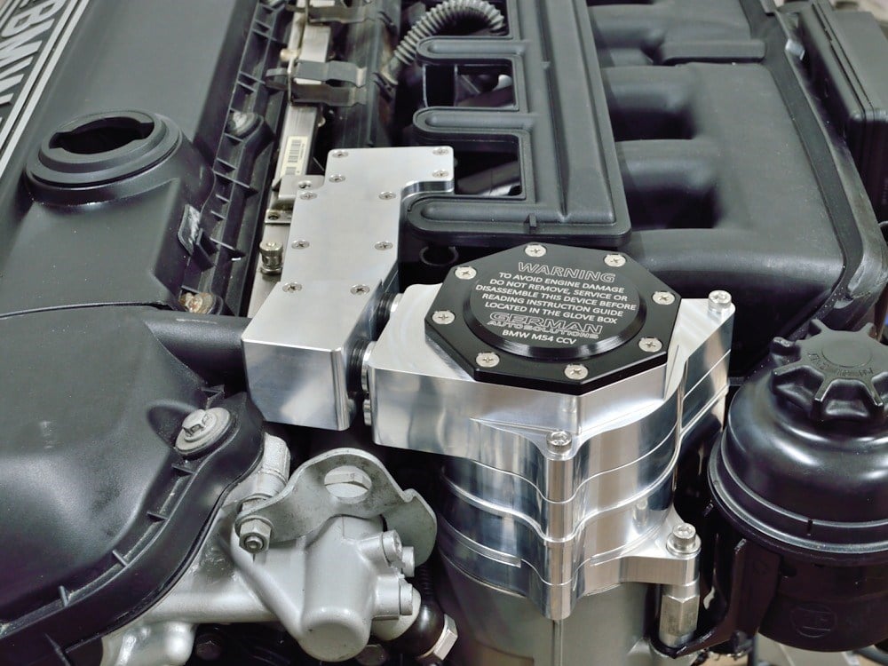
Congratulations, your German Auto Solutions CCV System installation is nearly completed.
#73
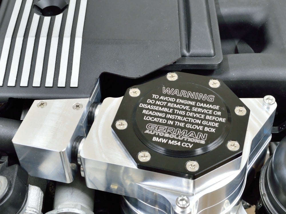
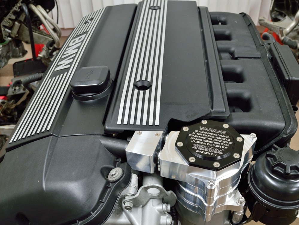
The final step of the installation is trimming the intake manifold cosmetic cover.
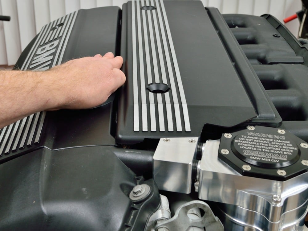
You can either just trim the underside of the outer lip of the cover where it sits on top of the docking manifold and CCV, or if you don’t want to have to remove the intake manifold cosmetic cover whenever you service the CCV during an oil change, you can trim the cover as shown in the picture to allow access to the left rear cap screw.
Once you have trimmed the cover to suit your preference you can reinstall the air box and any other components, connectors and trim pieces that were previously removed.
The installation is now complete and you can test your new G.A.S. CCV.
#74
Make sure all the tool have been removed from the engine bay and the crankcase has been refilled with engine oil if previously drained.
Make sure that the oil filler cap is on and tight then start the engine and listen for normal idle RPM. Visually check for any oil leaks around the base of the oil separator. Stop the engine if you see any oil leaking or hear anything abnormal and find the source of the problem.
The only place the G.A.S. CCV can leak oil is between the mounting base 100mm o-ring and the bottom inside lip of the oil separator.
#75
During this step do not rev the engine or blip the throttle with the oil filler cap removed. Only perform this test with the engine at a normal idle RPM.
If everything checks out OK, remove the oil filler cap then cover the valve cover hole with your hand. You should feel just a little bit of suction and a small in rush of air when you lift your hand off of the valve cover.
Thank for choosing a high quality, U.S. made German Auto Solutions Product.
If you have any suggestions on how to make these instructions better, or any feedback on the G.A.S. CCV kit, please don’t hesitate to contact us.