BMW E39-E60-E82-E90-F22-F30-G29 Series G.A.S. Monoballs Installation DIY
NOTE: These instruction are specific to installing a G.A.S. Monoball kit when using the German Auto Solutions Control Arm Bushing Tool while the control arms are still on the vehicle. These instruction can also be used when using a conventional hand or hydraulic press with the control arms removed from the vehicle; just substitute your bearing cups and arbor or hydraulic press where the G.A.S. pressing tool is referenced. When installing the kit using an external press tool make sure that you FOLLOW ALL INSTRUCTIONS related to prepping the control arms for the monoball installation, application of the primer/activator compound and locking agent, and any other step that is not specific to the G.A.S. Monoball Bushing Pressing Tool.
****** IMPORTANT - IMPORTANT - IMPORTANT - IMPORTANT - IMPORTANT ******
Warning – Installation of this product should only be performed by a licensed and ASE Certified Automotive Technician.
We highly recommend using a laptop computer or tablet at the vehicle location if possible. The ability to enlarge the pictures on a computer or tablet display will ensure that all the important detail information in the pictures will be visible.
The larger screen of a laptop or tablet is highly preferred to a Smart Phone! The pictures contain important details that would be very difficult to view properly on the smaller display of a smart phone.
Make sure that you read each step fully from beginning to end before you perform any part of a step. Some steps may contain multiple procedures, and some steps may contain information at the end of the step, that is crucial to completing the step properly
This procedure requires the vehicle to be raised in order to have clearance to work on underbody chassis components. Use only a certified automotive lift or certified automotive vehicle ramps to raise the vehicle for service. Do Not use hydraulic jacks or jack stands for obvious safety reasons. When working under a vehicle always wear safety glasses.
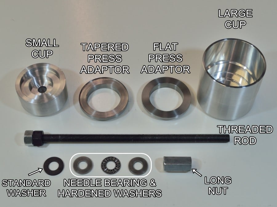
This is what is included in the German Auto Solutions bushing removal tool kit.
Take note of tool component descriptions for proper identification during instruction steps. Different tool components will be used during different steps.
NOTE – Always make sure that the needle bearing is kept clean and that it is always used with a thick hardened washer on each side.
Always keep the threaded rod away from dirt and contaminates.
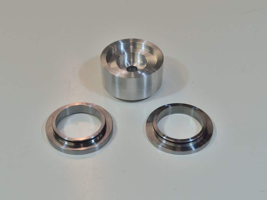
This is the small cup and the two styles of press adaptors.
The press adaptors sit in the cavity of the small cup. The rubber O-rings keep the adaptors held in place while using the tool.
Which press adaptor you will use will depend on which style of control arm bushings you have.
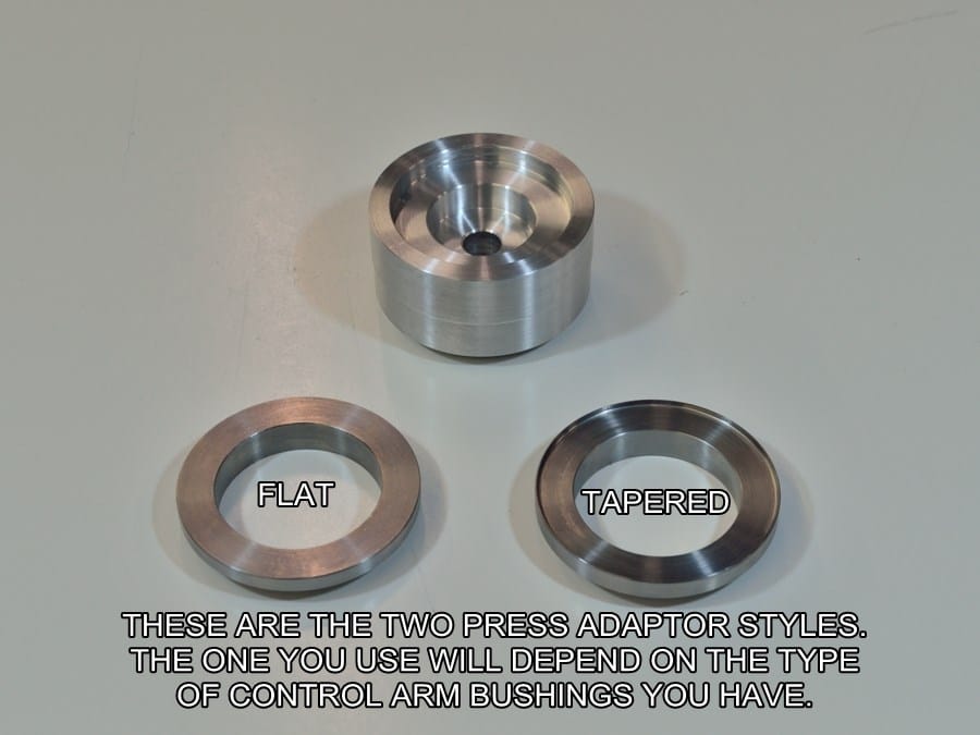
Here you can see the difference between the two styles of press adaptors.
The tapered adaptor is for use on OEM bushings with tapered ends.
The flat adaptor is for use on some aftermarket bushings and E90 M3 bushings with flat ends.
DO NOT use the wrong adaptor type when removing the bushings.
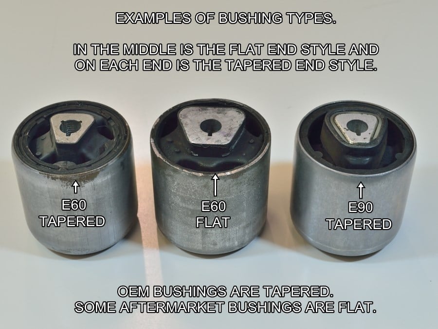
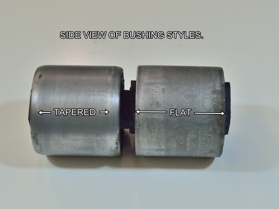
Here you can see the difference between the different bushing styles.
The ends of the OEM bushings are rolled over slightly to form a small taper. The aftermarket (Meyle) bushing shown has flat ends.
The OEM bushings with tapered ends are easier to remove because the tapered press adaptor will center itself over the end of the bushing.
Here is a side view of the two bushing styles.
When removing flat ended bushings the flat press adaptor has to be manually centered over the end of the bushing.
Extra care must be taken to make sure that a non-center tool does not gouge the inside of a control arm bore.
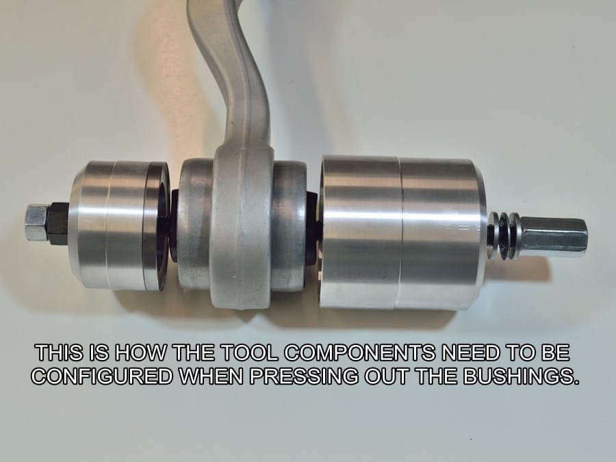
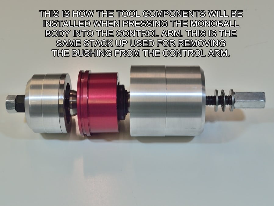
This picture shows the order of assembly for the tool components that will be required when you pull the stock bushing from the control arm. Note – Not all tool components are used for this procedure.
IMPORTANT – Make sure to use the correct press adaptor for your style of bushing. Only use the NON-FLAT adaptor on bushings with tapered ends as shown in the picture.
IMPORTANT – The standard washer goes behind the head of the puller bolt. The two thicker hardened washers go behind the nut, one on each side of the needle bearing. DO NOT mix any of these parts up or fail to include any of them when using the tool!
#1
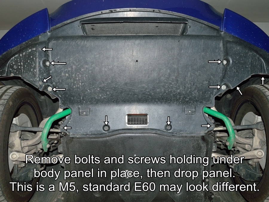
With the vehicle on a certified lift, start by removing the front underbody panel.
The picture shown here is of an E60 M5, other BMW models will vary slightly.
#2
Instructions will be given for the drivers side only. Repeat the instructions on the passenger side when instructed to do so.
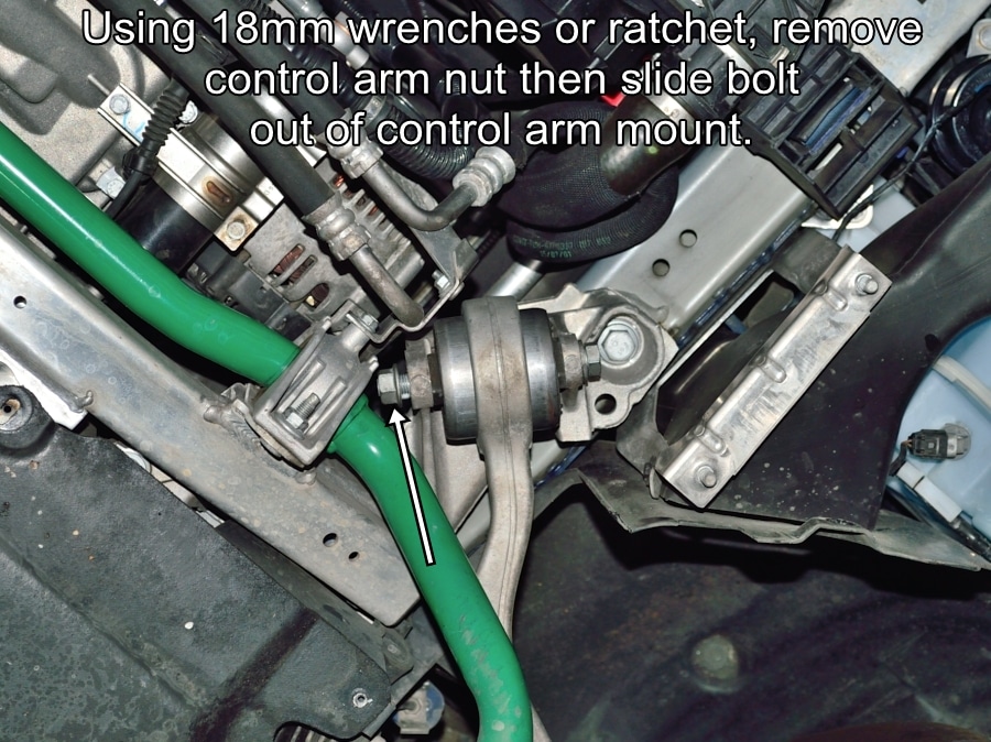
To drop the control from the sub frame mount, remove the nut shown. If you purchased new nuts discard the old nuts, they will not be reused.
The bolt head and nut are both 18mm on E60 & E90 models and 22mm on E39 models.
#3
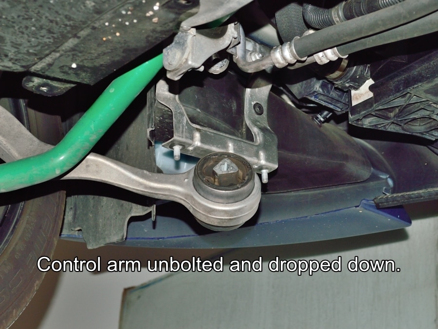
Remove the bolt from the control arm mount then pull down the control arm as shown.
#4
The stock rubber bushings need to be cleaned and lubed before pressing them through the control arm bores. There seems to be more clearance when pressing the bushings from the inboard side to the outboard side of the car. These instructions and all pictures will be shown removing the bushings in that direction.
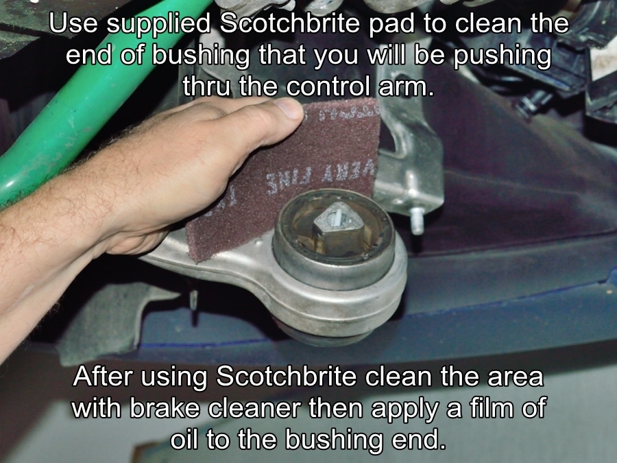
Thoroughly clean the O.D of the “INBOARD” end of the bushing with the provided Scotch-Brite pad as shown in the picture.
Clean the Scotch-Brited surface with brake cleaner or other solvent, then apply a film of oil or light grease to the ENTIRE cleaned surface. DO NOT SKIP THIS STEP!
There will be a lot of load placed on the puller tool during removal of the bushing. Cleaning and lubricating the bushing surface will help reduce those loads considerably.
Some Important Information about the German Auto Solutions Bushing Removal Rental Tool.
The German Auto Solutions bushing removal tool is a precision custom tool. The threaded rod and custom deep nut have fine and close tolerance precision threads. DO NOT lay the threaded rod on any dirty surface or expose it to any dirt or grit. Any grit allowed to get onto the threads can cause damage to the threads and possibly seize the nut to the rod.
DO NOT clean the threaded rod with solvent. The threads come pre-lubed with a red moly based grease which is required because of the high loads put on the threads during bushing removal. Use of solvent will wash away the lubrication. If the rod gets exposed to dirt or grit, lightly clean the threads with a soft clean cloth while trying not to remove the applied grease.
Remember, you will be held financially reasonable for any careless damage done to the tool components. If any parts of the tool kit are returned damaged the cost of those parts will be deducted from your security deposit.
#5
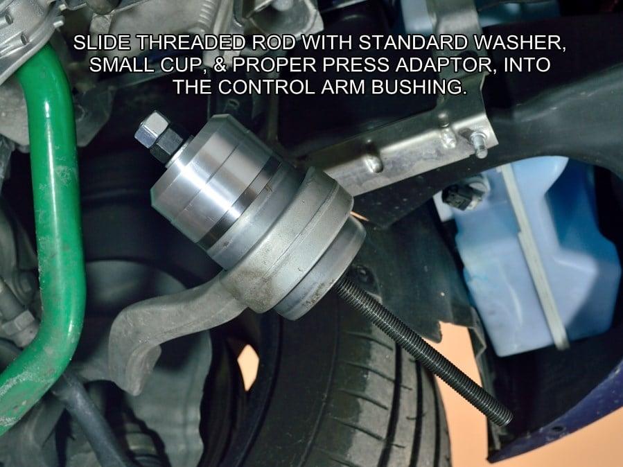
Install the correct bushing “press adaptor” that is required for the type of bushings that you are removing, into the small cup
Slide the puller tool threaded rod through the control arm bushing with the thin washer behind the rod bolt end and with smaller cup positioned as shown in the picture.
#6
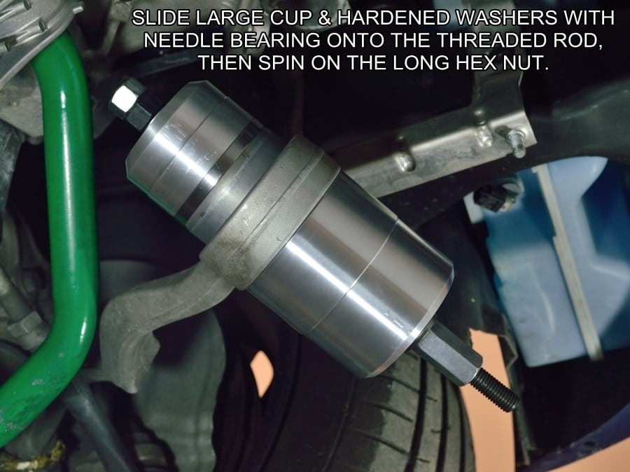
Slide the larger cup onto the opposite end of the threaded rod, followed by thick washer, needle bearing, thick washer, then nut.
If using the “Tapered Press Adaptor” center the recess over the tapered end of the OEM bushing.
If using the “Flat Press Adaptor” you will need to center the adaptor to end of the OEM bushing visually and by feel.
Note – After time the rubber I.D. of the bushing takes a set a little off center from the O.D., you need to make sure that the cup recess is surrounding the taper of the OEM bushing and not sitting a little “cock eyed” on it. If needed push the small cup in the direction it needs to move to center itself over the bushing taper while hand tightening the nut. You DO NOT want to use the tool if the small cup is not properly centered.
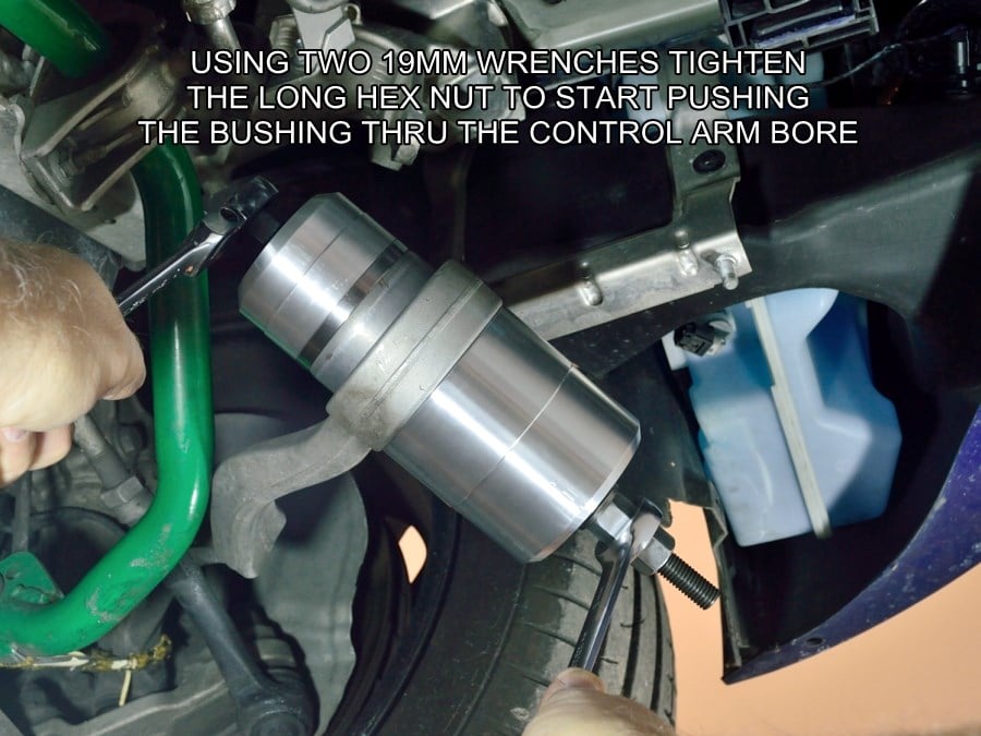
#7
The rod bolt head and long hex nut on the puller tool are both 19mm. You are going to want to hold the bolt head and turn the long hex nut.
Because even a deep well socket will be too short, I highly, highly recommend a “Gearwrench” to turn the nut. Without one you will get very tired repositioning a box end wrench. If you don’t have them you should get a set. You will never regret it. You can find them at Sears and many other tool sellers.
The bushing will take some force to start moving, but will get easier once broken loose.
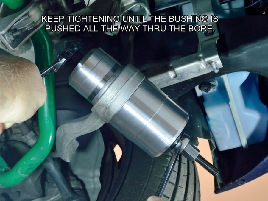
#8
Because of the fine pitch threads on the rod it will take a few minutes to pull the bushing all the way through the control arm.
If you are using the flat pressing adapter pay close attention to the centering of the adaptor as it enters the control arm bore. If the adapter is off center it will damage the bore of the control arm as it’s being pulled through.
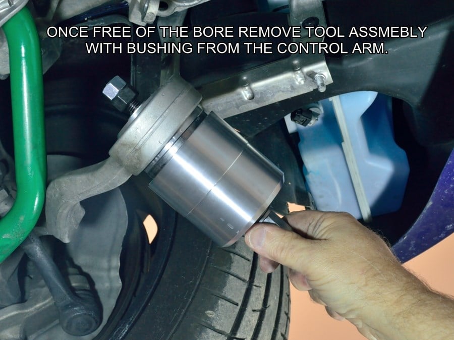
#9
Once free of the control arm, remove the puller tool with bushing.
IMPORTANT! – IMPORTANT! – IMPORTANT!
If you are installing the GAS Monoball Kit into an E82 1M, E90 M3, F22 or F30 series, or G29/Supra or any control arms that use an aluminum skinned factory bushing, CLICK HERE to follow addition instructions pertaining to these control arms.
If you are not sure about what you have, click the link to see sample images of the different bushing styles.
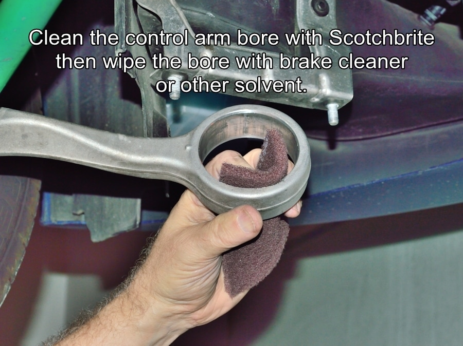
#10
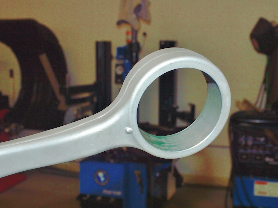
Using the supplied Scotch-Brite pad, thoroughly clean the inside of the control arm bore. After the Scotch-Brite, clean the bore with brake cleaner or solvent. Clean the outside of the Monoball housing with solvent at this time as well.
You can now move to the passenger side and repeat steps #2-#10.
#11
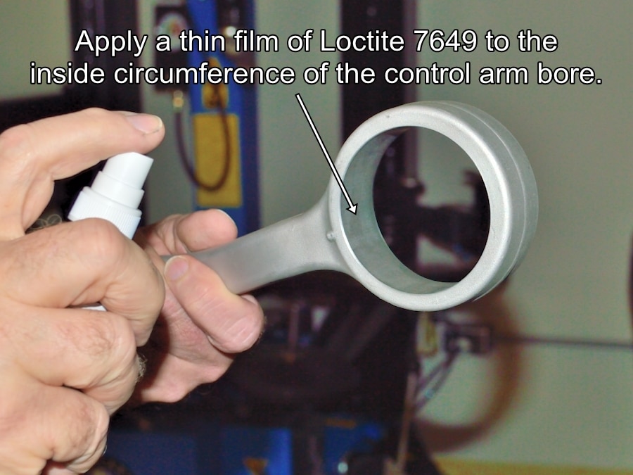
The picture in this step shows a spray bottle of Loctite 7649. That is no longer correct. The 7649 primer now comes in a small blue bottle.
After cleaning the control arm bore housing with solvent you will carefully apply a THIN film of Loctite 7946 primer around the inside walls of the control arm bore using the small gauze pad supplied with the kit. This is just an activator that aids in the curing of the locking compound, it is not the actual locking compound so you only need a very light coating. Wet the gauze pad with the primer from the small bottle. Wipe around the entire inside bore of the control arms.
NOTE-The bottle of Loctite 7649 contains more primer than what is required to properly coat the surfaces of the control arm bores and Monoball housings so you should have some left over when finished.
This control arm is shown removed from the vehicle because I forgot to take this picture at the proper time when these instruction were originally put together.blue
#12
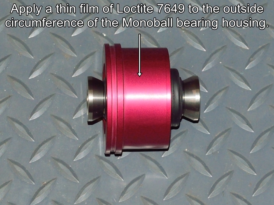
After cleaning the outside of the Monoball housing with solvent, using the supplied Loctite 7649 primer, wipe a thin film around the outer circumference of the Monoball bearing housing using the gauze pad. Again, use no more than 1/4 of the total bottle contents.
Allow approximately 15 minutes for the primer to dry before applying the Loctite 609 locking agent in following steps.
Repeat steps #12 and #13 on the passenger side components.
#13
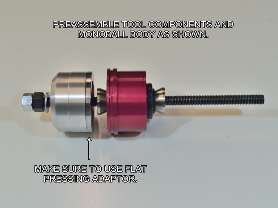
The fit between the bearing housing and the control rod bore is very precise. Use of the tool will guaranty that the bearing housing gets pulled in straight and won’t bind in the bore.
Make sure to use the Flat Press Adaptor to prevent any cosmetic damage to the Monoball housings during installation.
#14
After you slide the tool into the control arm bushing configured as shown in step #13, you will then slide the large cup, needle bearing assembly and install the long hex nut as shown.
You will not install the tool into the control arm bushing until step #16.
#15
Snip off the tip of one of the two supplied tubes of Loctite 609 sleeve locking compound. Note – Each tube will coat the inside of the one control arm bore and outside of one Monoball housing. DO NOT use more than one bottle of Loctite 609 per side of the car.
Apply the 609 compound a few drops at a time to the inside bore of the control arm. Using your finger, spread the compound evenly around the inside circumference of the bore. Add more drops until you have coated the entire area of the bore.
Repeat the process on the outside circumference of the Monoball bearing housing. Again, make sure that you coat the entire outer circumference of the housing.
Your 15 minute time limit has started, proceed immediately to the next step.
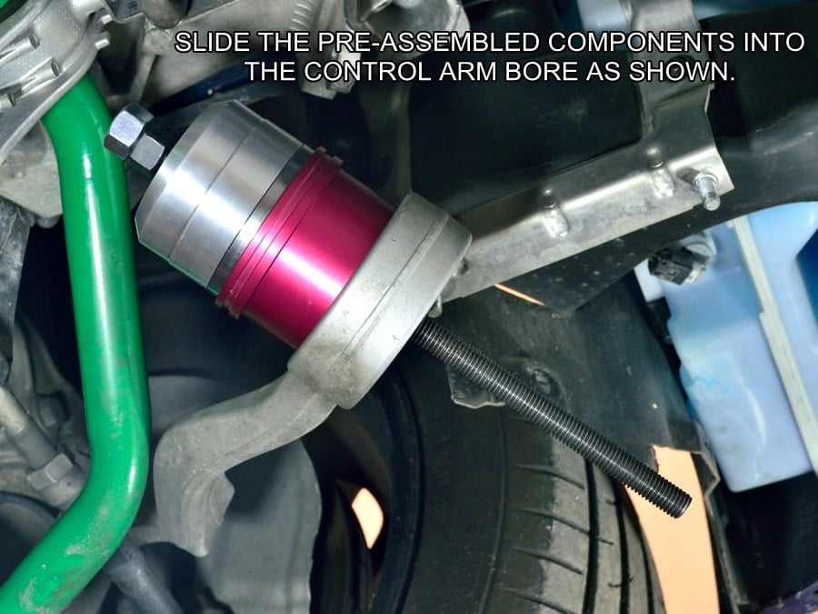
#16
Install the rod, small cup with flat press adaptor and Monoball housing into the control arm bore as shown.
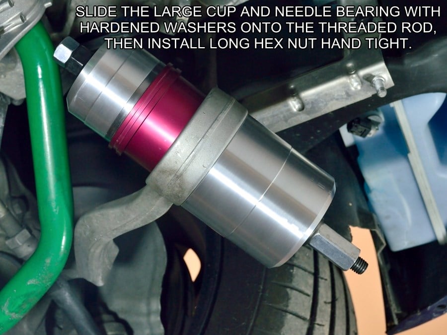
#17
Install large cup, needle bearing assembly, and long nut, then hand tighten.
Wiggle the large cup around while hand tightening the nut until the cup sits centered over the control arm bore as shown.
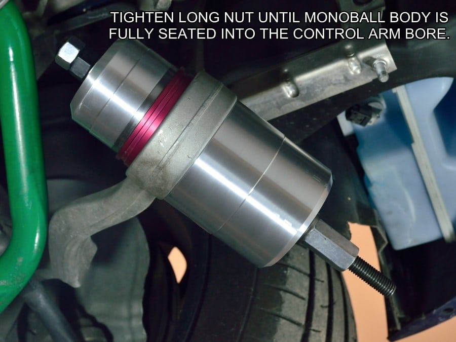
#18
While holding the bolt head end, tighten the long nut until the Monoball housing is fully seated. Tighten the tool nut firmly at the end to insure that the Monoball housing is fully seated into the control arm bore.
Remove the tool and wipe off any excess locking agent and activator.
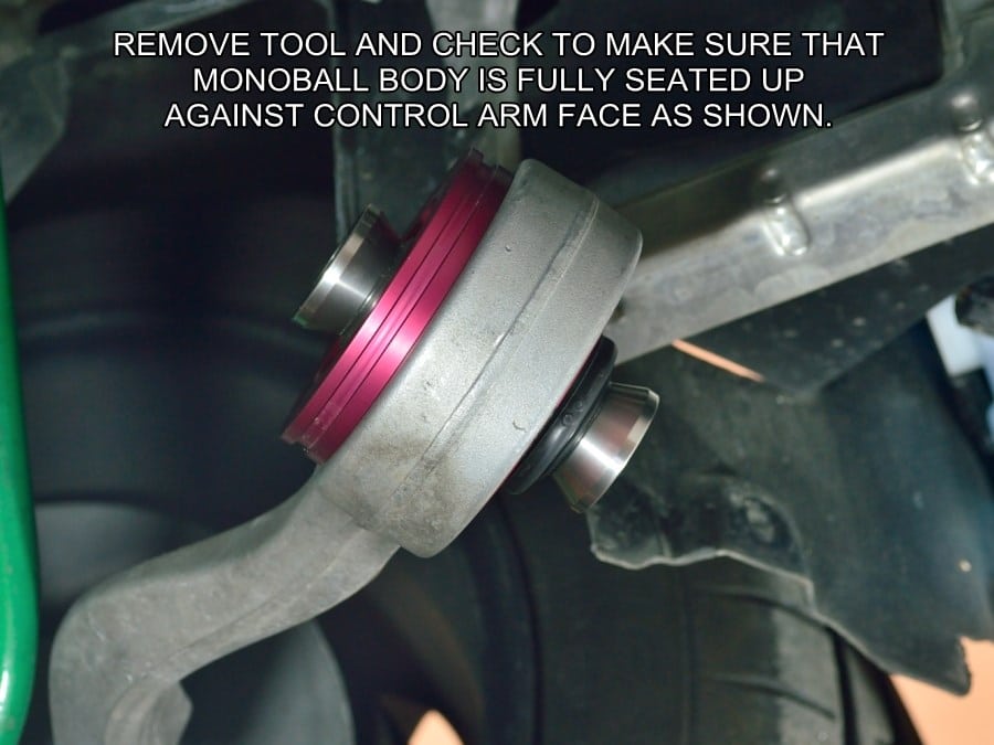
#19
Once the tool is removed, visually verify that the Monoball body is fully seated up against the control arm face as shown.
If Monoball housing is not fully seated against the control arm reinstall the tool and retighten until the housing is seated.
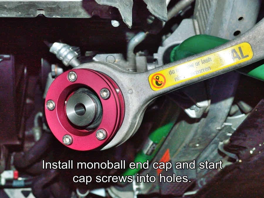
#20
Position the retaining cap, start the five screws, then tighten until finger tight.
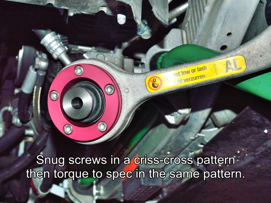
#21
Using a 5mm Allen wrench or hex driver hand tighten the five cap screws in a couple of steps in a star shaped pattern.
Use a final tightening torque = 10.8Nm – 8.0lb/ft.
Carefully examine the “non-bolt” side of the monoball housing to again make sure that the housing flange has been fully drawn up against the control arm surface.
#22
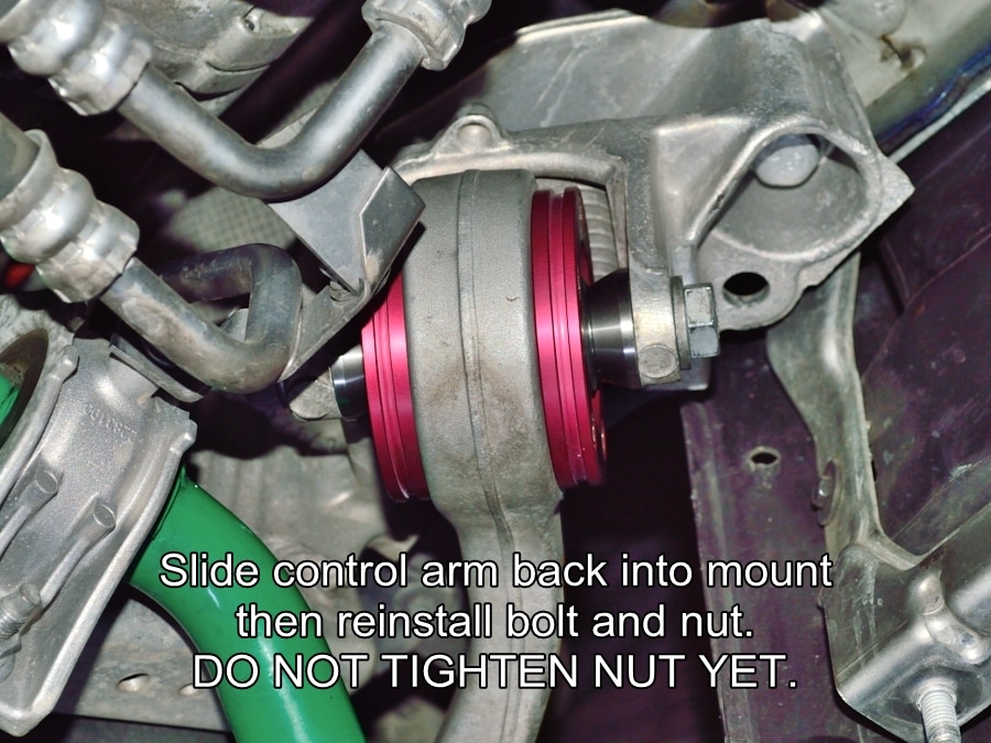
Reposition the control arm into the sub frame mount and reinstall factory bolt. You may have to rotate the ball joint slightly within the housing if it’s not square to the mounting flanges.
New ball joints are pretty stiff so you will need to push a large screwdriver or something similar through the center of the ball joint to get enough leverage to rotate it.
On E39 models you will need to slide the spacers into place as you install the thru bolt. It’s easiest to start the bolt into one spacer first to hold it in place, then slide the control arm into place and push the bolt in a little further, then position the last spacer and slide the bolt the rest of the way.
Install the new lock nut, tighten until just snug, then loosen about half a turn.
#23
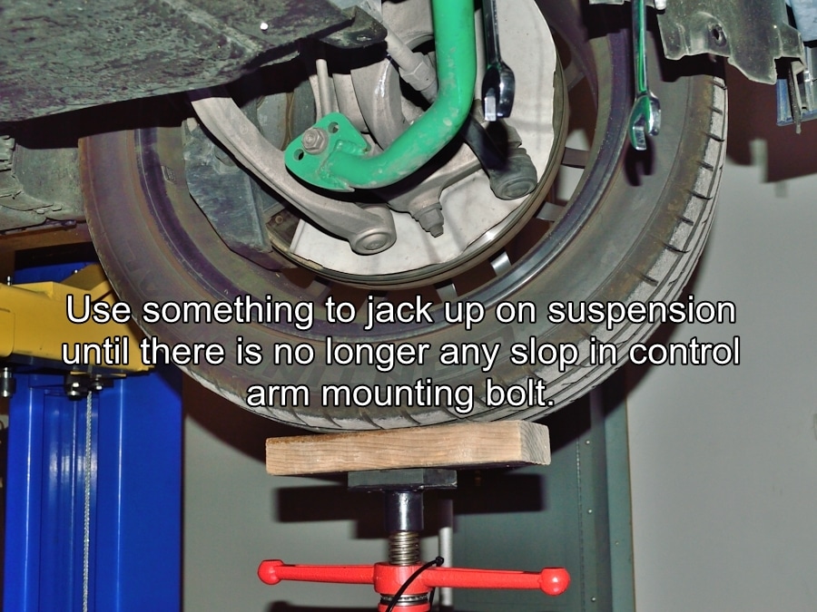
You will want to take up any slop in the control arm mounting before torquing the nut. Use some means to apply upward pressure on the suspension until the control arm feels like it can no longer wiggle in the sub frame mount.
You do not need to have the full weight of the vehicle resting on the control arms before tightening like you do when installing new rubber bushings. You just need enough pressure to take the slop out of the sub frame mounting hardware.
#24
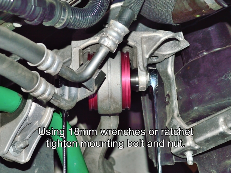
While under pressure, tighten, then torque the mounting bolt and nut.
Torque = 100Nm – 74ft/lb plus 90 degrees.
You can now move to the passenger side and complete steps #16-#24.
Reinstall any under body panels and anything else that was removed but not covered in these instructions. Return your car to ground level and enjoy the improved handling precision.
Thank you for choosing a German Auto Solutions product! If you are pleased with the quality of our product, our instructions and our customer support, we would be grateful for positive feedback on our website or a forum or Facebook post regarding this product.